Abstract
This document specifies version 1.2 of the Scalable Vector Graphics (SVG) Language, a modularized language for describing two-dimensional vector and mixed vector/raster graphics in XML.
Status of this Document
This section describes the status of this document at the time of its publication. Other documents may supersede this document. A list of current W3C publications and the latest revision of this technical report can be found in the W3C technical reports index at http://www.w3.org/TR/.
This document is the fourth public working draft of the SVG 1.2 specification. It lists the areas of new work in version 1.2 of SVG and is not a complete language description. The SVG Working Group consider the feature set of SVG 1.2 to be approaching stability. However, there are some cases where the descriptions in this document are incomplete and simply show the current thoughts of the SVG Working Group on the feature, or list the open issues. Therefore, this document should not be considered stable.
This version does not include the complete implementations of SVG 1.2 in either DTD or XML Schema form. Those will be included in subsequent versions, once the content of the SVG 1.2 language stabilizes. This document references a draft RelaxNG schema for SVG 1.1.
This document has been produced by the W3C SVG Working Group as part of the W3C Graphics Activity within the Interaction Domain.
We explicitly invite comments on this specification. Please send them to www-svg@w3.org: the public email list for issues related to vector graphics on the Web. This list is archived and acceptance of this archiving policy is requested automatically upon first post. To subscribe to this list send an email to www-svg-request@w3.org with the word subscribe in the subject line.
The latest information regarding patent disclosures related to this document is available on the Web. As of this publication, the SVG Working Group are not aware of any royalty-bearing patents they believe to be essential to SVG.
Publication as a Working Draft does not imply endorsement by the W3C Membership. This is a draft document and may be updated, replaced or obsoleted by other documents at any time. It is inappropriate to cite this document as other than work in progress.
1 How to read this document and give feedback
This draft of SVG 1.2 is a snapshot of a work-in-progress. The SVG Working Group believe the most of the features here are complete and stable enough for implementors to begin work and provide feedback. Some features already have multiple implementations.
This is not a complete specification of the SVG 1.2 language. Rather it is a list of features that are under consideration for SVG 1.2. In many cases the reader will have to be familiar with the SVG 1.1 language.
The main purpose of this document is to encourage public feedback. The best way to give feedback is by sending an email to www-svg@w3.org. Please include some kind of keyword that identifies the area of the specification the comment is referring to in the subject line of your message (e.g "1.2 compositing" or "1.2 audio and video formats"). If you have comments on multiple areas of this document, then it is probably best to split those comments into multiple messages.
The public are welcome to comment on any aspect in this document, but there are a few areas in which the SVG Working Group are explicitly requesting feedback. These areas are noted in place within this document. There are also a few areas related to the specification that are listed here:
-
An W3C XML Schema for SVG 1.2. We are currently developing a W3C XML
Schema, demonstrated by some of the schema snippets included in
this document. The current plan is to follow the technique of
XHTML Modularization in XML Schema for SVG. It is expected that future versions of this specification
will include a schema in RelaxNG format also.
-
How should elements be described in the specification? Previous
SVG specification have included relevant DTD snippets when defining
an element. This document has incomplete (and incorrect) XML Schema
snippets. Are these useful? As the schema becomes more complete and
as the modularization information is included, the snippets may
become longer and potentially less readable. An alternative would
be to not use schema snippets and instead use a more abstract
definition of element contents and attributes.
-
The format of the specification itself is under consideration. A
full SVG specification can be over 800 printed pages. Suggestions
are welcome on alternate ways to arrange the information, such as
separate downloads for the DOM Interfaces, DTD/Schema, etc. Note
that the complete online HTML version will always be the normative
reference, regardless of the availability of alternate downloads.
The current plan is to separate the specification into a number
of parts such as Part 1: Introduction, structure and graphics,
Part 2: Dynamic SVG, scripting, extensibility and animation,
Part 3: Conformance and Appendix, Part 4: DOM Interfaces, Part 5:
Schema, Part 6: Index.
2 SVG for images and applications
The SVG Working Group is chartered to develop a language that best addresses the needs of its user community. After carefully examining the past and present use of SVG as well as researching the expected future uses of SVG, the SVG Working Group can see two broad usage themes:
There has been much discussion within the SVG Working Group on how to best accomodate the two different usage themes. Some Working Group members have expressed concerns regarding potential incompatibility of the two themes, especially in the area of graphical authoring tools. Other members believe some of the new features of SVG 1.2 directly address these incompatibilities.
There are a number of choices that the SVG Working Group could take on this issue. Here are some examples:
-
Create a new profile of SVG around graphical assets. This profile
would focus on the core graphical language features around the
interchange, display and print workflows. In such a profile there
would be no scripting or extensibility.
-
Create a new profile of SVG that provides a strict graphical language.
This profile would remove optional features and the extensibility
features of SVG. DOM Scripting would be allowed.
-
Create workflow-specific SVG profiles. Some examples of these
profiles could be: a clipart profile, a "streaming movie" animation
profile (no scripting, unidirectional timeline), a clipboard
exchange profile, a technical graphics profile, a graphics design
interchange profile and an XSL-FO master page profile.
-
Change the SVG conformance criteria. Instead of creating more
profiles/flavors of SVG, it might be possible to increase the
awareness of the conformance criteria. Possibly make a distinction
between an SVG document intended for exchange and one intended for
applications.
-
Implement a new document structure for the SVG specification by
publishing multiple parts. For example, SVG Part 1 could define the
core static SVG features; SVG Part 2 could introduce SMIL animation
and interactivity; SVG Part 3 could define the SVG DOM; and finally
Part 4 would cover the extensibility.
-
Separating the language into two themes and reorganize the
specification around those themes (as described in option 5). This
is currently the favored choice of the SVG Working Group and is
described below.
-
Provide tighter control over the allowed contents of any SVG
file, in effect allowing the author to create a profile.
Each SVG file would explicitly say what features are allowed
and, therefore, what features are prohibited in a file.
Over time, certain industry areas may converge on a set
of document templates.
There could be predefined keywords that avoid listing all
the supported modules.
-
No change to the specification; Add the new SVG 1.2 features but
otherwise leave the SVG language as it.
The SVG Working Group is seeking feedback on this matter from both users and implementers. Which changes, if any, should the Working Group be making to ensure a good user experience when using SVG for both of the usage themes described above.
It is worth noting that the SVG Working Group have a strong desire to keep the number of SVG profiles to a minimum.
2.1 Possible theming of the SVG language
This section describes the currently favored choice of the SVG Working Group: separating the SVG language into two themes.
Separating the language into two themes does not add any new features, nor does it create two new languages. Rather it better distinguishes the two broad usages of the SVG language. SVG Core files will be interoperable between all compliant user agents and authoring tools. SVG Extended files will be interoperable between all compliant extended user agents and potentially between authoring tools.
It is expected that the SVG specification will continue as a single document, but will be separated into a number of sub-documents. For example, the SVG Core features, the SVG Extended features and the SVG DOM may be available as separate files.
The SVG Working Group is considering many different methods of identifying the SVG themes, taking into account the existing SVG content. One proposed solution is to have an attribute on the root svg element that identifies an SVG Core document. By default the attribute is set to identify the document as SVG Extended. Also, there will be clarifications in the conformance criteria.
During the evolution of this solution, the SVG Working Group considered a number of other potential identification techniques, such as:
-
Different MIME types. For example SVG Core could use "image/svg+xml" and
SVG Extended could use "application/svg+xml". However, this would
require significant changes to existing server configuration, as well
as potentially cause existing content to be handled incorrectly.
-
Different File extensions.
-
Two profiles of SVG.
3 Text Enhancements
3.1 Text Wrapping
SVG 1.2 enables a block of text to be rendered inside a shape, while automatically wrapping the text into lines, using the flowText element. The idea is to mirror, as far as practical, the existing SVG text elements.
3.1.1 The flowText element
The flowText element specifies a block of text to be rendered. It contains at least one flowRegion element, defining regions in which the child flowDiv element of the flowText should be flowed into.
The following is an extract of an XML Schema that describes the flowText element.
<xs:element name="flowText">
  <xs:complexType>
    <xs:sequence>
      <xs:element ref="flowRegion"/>
      <xs:element ref="flowRegionExclude"/>
      <xs:element ref="flowDiv"/>
    </xs:sequence>
    <xs:attributeGroup ref="PresentationAttrs"/>
    <xs:attributeGroup ref="StyleAttrs"/>
  </xs:complexType>
</xs:element>
3.1.2 The flowRegion element
The flowRegion element contains a set of shapes and exclusion regions in which the text content of a parent flowText element is drawn into. A flowRegion element has basic shapes and path elements as children, as well as a flowRegionExclude element. The children of a flowRegion element are inserted into the rendering tree before the text is drawn, and have the same rendering behavior as if they were children of a g element.
The child elements create a sequence of shapes in which the text content for the parent flowText will be drawn into. Once the text fills a shape it flows into the next shape. The flowRegionExclude child describes a set of regions in which text will not be drawn into, such as a cutout from a rectangular block of text.
The child elements of a flowRegion can be transformed as usual, but the text is always laid out in the coordinate system of the flowText element. For example, a rect child with a 45 degree rotation transformation will appear as a diamond, but the text will be axis aligned.
The following is an extract of an XML Schema that describes the flowRegion element.
<xs:element name="flowRegion">
  <xs:complexType>
    <xs:sequence>
      <xs:choice>
        <xs:group ref="ShapeElements" minOccurs="0" maxOccurs="unbounded"/>
        <xs:element ref="use" minOccurs="0" maxOccurs="unbounded"/>
        <xs:group ref="flowRegionExclude" minOccurs="0" maxOccurs="unbounded"/>
      </xs:choice>
    </xs:sequence>
  </xs:complexType>
</xs:element>
3.1.3 The flowRegionExclude element
The flowRegionExclude element contains a set of shapes defining regions in which flowed text is not drawn. It can be used to create exclusion regions from within a region of text.
If flowRegionExclude is a child of a flowRegion then it describes an exclusion region for that particular flowRegion. If it is a child of flowText then it describes exclusion regions for all flowRegion children of the flowText.
The following is an extract of an XML Schema that describes the flowRegionExclude element.
<xs:element name="flowRegionExclude">
  <xs:complexType>
    <xs:sequence>
      <xs:group ref="ShapeElements" minOccurs="0" maxOccurs="unbounded"/>
      <xs:element ref="use" minOccurs="0" maxOccurs="unbounded"/>
    </xs:sequence>
  </xs:complexType>
</xs:element>
3.1.4 The flowDiv element
The flowDiv element specifies a block of text to be inserted into the text layout, and marks it as a division of related text. The children of the flowDiv element will be rendered as a block: offset before and after from their parent's siblings. By separating the logical order of text (in successive flowDiv elements) from the physical layout (in regions, which can be presented anywhere on the canvas) the SVG document structure encourages creation of a default, meaningful linear reading order while preserving artistic freedom for layout. This enhances accessibility.
The following is an extract of an XML Schema that describes the flowtext element.
<xs:element name="flowDiv">
  <xs:complexType>
    <xs:choice minOccurs="0" maxOccurs="unbounded">
      <xs:element ref="flowPara"/>
      <xs:element ref="flowRegionBreak"/>
    </xs:choice>
    <xs:attributeGroup ref="PresentationAttrs"/>
    <xs:attributeGroup ref="StyleAttrs"/>
  </xs:complexType>
</xs:element>
3.1.5 The flowPara element
The flowPara element marks a block of text as a logical paragraph.
The following is an extract of an XML Schema that describes the flowPara element.
<xs:element name="flowPara">
  <xs:complexType mixed="true">
    <xs:choice minOccurs="0" maxOccurs="unbounded">
      <xs:element ref="flowRegionBreak"/>
      <xs:element ref="flowLine"/>
      <xs:element ref="flowTref"/>
      <xs:element ref="flowSpan"/>
      <xs:element ref="flowImage"/>
    </xs:choice>
    <xs:attributeGroup ref="PresentationAttrs"/>
    <xs:attributeGroup ref="StyleAttrs"/>
  </xs:complexType>
</xs:element>
3.1.6 The flowSpan element
The flowSpan element specifies a block of text to be rendered inline, and marks the text as a related span of words. The flowSpan element is typically used to allow a subset of the text block, of which it is a child, to be rendered in a different style, or to mark it as being in a different language.
The following is an extract of an XML Schema that describes the flowSpan element.
<xs:element name="flowSpan">
  <xs:complexType mixed="true">
    <xs:choice minOccurs="0" maxOccurs="unbounded">
      <xs:element ref="flowSpan"/>
      <xs:element ref="flowLine"/>
      <xs:element ref="flowImage"/>
      <xs:element ref="flowRegionBreak"/>
    </xs:choice>
    <xs:attributeGroup ref="PresentationAttrs"/>
    <xs:attributeGroup ref="StyleAttrs"/>
  </xs:complexType>
</xs:element>
3.1.7 The flowRegionBreak element
When the flowRegionBreak element is inserted into the text stream it causes the text to stop flowing into the current region at that point. The text after the flowRegionBreak element begins in the next region. If there is no next region, then the text will stop being rendered at the point of the flowRegionBreak.
The following is an extract of an XML Schema that describes the flowRegionBreak element.
<xs:element name="flowRegionBreak">
  <xs:complexType/>
</xs:element>
3.1.8 The flowLine element
The flowLine element is used to force a line break in the text flow. The content following the end of a flowLine element will be placed on the next available strip in the flowRegion that does not already contain text. This happens even if the flowLine element has no children.
Note that if there are no printing characters between the end of multiple flowLine elements the second and greater flowLine elements have no effect as the current line does not contain any text when they are processed.
In all other aspects, the flowLine element is functionally equivalent to the flowSpan element.
The following is an extract of an XML Schema that describes the flowLine element.
<xs:element name="flowLine">
  <xs:complexType mixed="true">
    <xs:choice minOccurs="0" maxOccurs="unbounded">
      <xs:element ref="flowSpan"/>
      <xs:element ref="flowLine"/>
      <xs:element ref="flowImage"/>
      <xs:element ref="flowRegionBreak"/>
    </xs:choice>
    <xs:attributeGroup ref="PresentationAttrs"/>
    <xs:attributeGroup ref="StyleAttrs"/>
  </xs:complexType>
</xs:element>
3.1.9 The flowTref element
The flowTref element is used to insert the child text content of a referenced element. It's effect is analogous to the tref element.
The following is an extract of an XML Schema that describes the flowTref element.
<xs:element name="flowTref">
  <xs:complexType>
    <xs:attribute ref="href" use="required"
        namespace="http://www.w3.org/1999/xlink"/>
    <xs:attributeGroup ref="PresentationAttrs"/>
    <xs:attributeGroup ref="StyleAttrs"/>
  </xs:complexType>
</xs:element>
3.1.10 The flowRef element
The flowRef element references a flowRegionElement. It causes the referenced element's geometry to be drawn in the current user coordinate system along with the text that was flowed into the region.
The following is an extract of an XML Schema that describes the flowRef element.
<xs:element name="flowRef">
  <xs:complexType>
    <xs:attribute ref="href" use="required"
        namespace="http://www.w3.org/1999/xlink"/>
    <xs:attributeGroup ref="PresentationAttrs"/>
    <xs:attributeGroup ref="StyleAttrs"/>
  </xs:complexType>
</xs:element>
3.1.11 The flowImage element
The flowImage element defines a container for graphics which are to be rendered inline in the text layout. It can be used to insert images or any other graphic object that will then flow inline with the text flows.
The flowImage element establishes a new viewport for contained graphic elements. If flowImage specifies an absolute size, that size is used as the bounding rectangle for the flowImage region. If flowImage specifies a percentage as its size, the percentage is represented as a percentage of the current viewport.
In the absence of either width or height on the flowImage element, no new viewport is established. Any contained graphic elements are sized relative to the current viewport. In that case, the bounds of the flowImage element are calculated from the bounding box of any contained child graphic elements.
The following is an extract of an XML Schema that describes the flowImage element.
<xs:element name="flowImage">
  <xs:complexType mixed="true">
    <xs:choice minOccurs="0" maxOccurs="unbounded">
      <xs:element ref="image"/>
      <xs:group ref="ShapeElements"/>
      <xs:element ref="g"/>
    </xs:choice>
    <xs:attribute name="width" type="CoordinateType" use="optional"/>
    <xs:attribute name="height" type="CoordinateType" use="optional"/>
  </xs:complexType>
</xs:element>
3.1.12 Text Flow
Text flow is defined as a post processing step to the standard text layout model of SVG. At a high level the steps for flowing text are as follows:
-
The text is then processed in logical order to determine line
breaking opportunities between characters, according to Unicode
Standard Annex No. 14
-
Text layout is performed as normal, on one infinitely long line,
soft hyphens are included in the line. The result is a set of
positioned Glyphs.
-
Glyphs are associated with the word who's characters generated it.
In cases where characters from multiple words contribute to the same
glyph the words are merged and all the glyphs are treated as part of
the earliest word in logical order.
-
The glyphs from a word are collapsed into Glyph Groups. A Glyph
Group is comprised of all consecutive glyphs from the same word. In
most cases each word generates one glyph group however in some cases
the interaction between BIDI and special markup may cause glyphs
from one word to have glyphs from other words embedded in it.
-
Each Glyph Group has two extents calculated: is it's normal extent,
and it's last in text region extent. It's normal extent is the sum
of the advances of all glyphs in the group except soft hyphens. The
normal extent is the extent used when a Glyph Group from a later
word is in the same text region. The last in text region extent
includes the advance of a trailing soft hyphens but does not include
the advance of trailing whitespace or combining marks (ABC width?).
The last in text region extent is used when this glyph group is from
the last word (in logical order) in this text region.
-
The location of the first strip is determined based on the first
word in logical order (see Calculating Text Regions and determining
strip location).
-
Words are added to the current Strip in logical order. All the
Glyph Groups from a word must be in the same strip and all the
glyphs from a Glyph Group must be in the same Text Region.
When a word is added the line height may increase, it can never decrease from the first word. An increase in the line height can only reduce the space available for text placement in the span.
The span will have the maximum possible number of words.
-
The Glyphs from the Glyph Groups are then collapsed into the text
regions by placing the first selected glyph (in display order) at
the start of the text region and each subsequent glyph at the
location of the glyph following the preceding selected glyph (in
display order).
-
The next word is selected and the next strip location is determined.
Goto Step 7.
3.1.13 Determining Strip Location
To determine the placement of a strip the Glyph Groups from first word is used. The initial position for the strip is calculated, taking into account the end (in non text progression direction) of the previous strip and the appropriate margin properties.
The line-box is calculated using the initial position as the top/right edge of the line-box, and the line-height of the first word. The 'bottom/right' edge of the line-box must be checked against the margin properties, if it lies within the margin then processing moves to the next flow region.
Once the line-box is calculated the Strip and it's associated Text Regions are calculated (see: Calculating Text Regions). If the first word can be placed in the text regions of this Strip then this location is used for the next line of text. If the first word does not fit then the top/right edge is shifted by 'line-advance' and the new line-box is checked. This proceeds until the word fits or end of the flow region is reached at which point processing moves to the next flow region.
3.1.14 Calculating Text Regions
In order to flow text into arbitrary regions it is necessary to calculate what areas of the arbitrary region are available for text placement. SVG uses a fairly simple algorithm to do this.
In summary you intersect the flow region geometry with the current line-box. The result of this intersection is referred to as the strip. The strip is then split into text regions where ever a piece of geometry from the flow region 'intrudes'. It is important to ignore edges & points that are co-incident with the top or bottom of the line-box.
The diagram below shows the text strips used on a given shape.
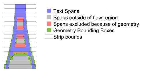
The following is the algorithm with more detail:
The current flow region and any applicable exclude regions must be combined into one piece of geometry, simply concatenating the geometry is sufficient as this entire algorithm deals simply with segments of the paths and does not use directionality information until the inclusion tests at the end. The result of the concatenation of the geometry is referred to as the flow geometry.
Next the line-box is calculated, from the top/right edge of the line, the line-height and the bounding box of the flow region. This line-box is intersection with the flow geometry, clipping the flow geometry segments to the line box.
The bounding box is then calculated separately for each of the segments in the intersection.
The left and right (top and bottom respectively for vertical text) edges of the bounding boxes are sorted in increasing coordinate order (x for horizontal text, y for vertical text), for edges at the same location the left/top (or opening) edge is considered less than right/bottom (or closing) edges. The following pseudo code then generates the list of open areas for the current line:
        Edge [] segs = ...; // The sorted list of edges.

        Edge edge = segs[0];
        int count = 1;
        double start = 0;
        for (i=1; i<segs.length; i++) {
            edge = segs[i];
            if (edge.open) {
              // 'open' is true, this is the start of a block out region.
                if (count == 0) {
                    // End of an open region so record it.
                    rgns.add(new TextRegion(start, edge.loc));
                }
                count++;
            } else {
              // 'open' is false, this edge is the end of a block out region.
                count--;
                if (count == 0) {
                    // start of an open area remember it.
                    start = edge.loc;
                }
            }
        }
This gives the regions of the strip that are unobstructed by any flow geometry (from either exclusion or flow regions), however those regions may be outside the flow region (such as in a hole, such as the middle of an 'O'), or inside an exclusion region. Thus the center of each rectangle should be checked first to see if it lies inside any exclusion region if so the rectangle is removed from the list. Second it must be checked for inclusion in the flow region, if it is inside the flow region then the rectangle is available for text placement and becomes a text region for the current strip.
Once all the text regions for a strip are located left and right Margins for horizontal text (top and bottom margins for vertical) as well as indent are applied. Margins are applied to each text region. For the first span in a paragraph (flowPara for flowRegionBreak) the indent is added to the appropriate margin of the first text region. For left to right text this is the left margin of the left most text region, for right to left text this is the right margin of the right most text region, and for vertical text is the top margin of the top most text region.
this is applying margins to every Text Region we could just apply them to the first/last text regions. Perhaps have a separate property for 'internal' margins and the 'external' margins?.
If the left/right (top/bottom) edges of a text region pass each other due to the application of margins (or indent) the text region is removed from the list. If the text region removed had indent applied the indent is not applied to the next text region in text progression direction it is simply ignored.
We could have the indent move but it isn't clear that this would always be correct. The above is simpler and for the cases where indent is most commonly used, simple rectangles, it doesn't matter.
Should we restrict indent's range such that it can be no more negative than the margin it is applied to? Our feeling is no. If the user wants to shift the boxes out they should be able to - the only complication this adds is that the geometry may no longer define the bounding box of the text.
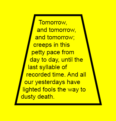
Below is an example of the flowing text capabilities:
<svg xmlns:svg="http://www.w3.org/2000/svg" version="1.2"
     xmlns:xlink="http://www.w3.org/1999/xlink"
  width="100%" height="100%" viewBox="0 0 300 310">
  <title>Basic textflow</title>
  <rect x="0" y="0" width="100%" height="100%" fill="yellow"/>
  <flow font-size="16">
    <flowRegion>
      <path d="M100,50L50,300L250,300L300,50z"/>
    </flowRegion>
    <flowDiv>
      <flowPara>Tomorrow, and tomorrow, and tomorrow; creeps in this
       petty pace from day to day, until the last syllable of recorded time.
       And all our yesterdays have lighted fools the way to dusty death.
     </flowPara>
    </flowDiv>
  </flow>
  <path d="M90,40L40,270L260,270L210,40z" fill="none" stroke="black" stroke-width="5"/>
</svg>
View this image as SVG (SVG-enabled browsers only)
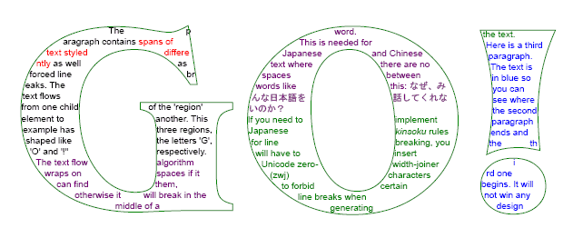
A more complicated example is show below. It is not included inline. Please see the SVG file for the source.
View this image as SVG (SVG-enabled browsers only)
3.2 Editable Text Fields
There are many SVG use cases where textual input is a requirement. Implementing such a feature in SVG 1.1 with the DOM is nearly impossible without restricting functionality, such as only allowing latin left-to-right text.
SVG 1.2 introduces editable text fields, moving the burden of text input and editing to the user agent, which has access to system text libraries.
3.2.1 The editable attribute
The text and flowDiv elements have an editable attribute which defines if the contents of the elements can be edited in place.
-
editable = "true" | "false"
-
If set to "false" the contents of the text element are not editable in place through the user agent. If set to "true", the user agent must provide a way for the user to edit the content of the text element and all contained subelements which are not hidden (with visibility="hidden") or disabled (through the switch element or display="none"). The user agent must also provide a way to cut the selected text from the element and to paste text from the clipboard into the element. If no value is given for this attribute, the default value is "false". Animatable: Yes.
In general, user agents should allow for the inline WYSIWYG editing of text with a caret that identifies current position.
For WYSIWYG editing the following functionality must be made available:
-
movement to the next/previous character (in logical order) with
Left/Right arrows for horizontal text and Down/Up keys for vertical
text
-
movement to the next/previous line with the Down/Up keys for horizontal
text and Right/Left for vertical text
-
movement to the beginning of the line with the Home key
-
movement to the end of the line with the End key
-
the system-dependent keyboard binding for copy/cut/paste
For devices without keyboard access, the equivalent system input methods should be used wherever possible to provide the functionality described above.
The content of the DOM nodes that are being edited should be live at all times and reflect the current state of the edited string as it being edited (except for the state associated with an Input Method Editor window).
4 Rendering Custom Content
SVG 1.2 adds the ability to associate behavior or extensions with arbitrary XML markup within an SVG file. This feature is referred to as Rendering Custom Content (RCC).
4.1 Element definitions
4.1.1 The extensionDefs element
The extensionDefs element registers a set of custom elements, all of which are in the same namespace.
The extensionsDefs element can be used in either of two ways. First, the custom elements can be defined within the content of the extensionDefs element, most significantly via elementDef child elements. Here is an example which defines two custom elements, equilateral-triangle and rhombus, in the "http://example.org" namespace:
<extensionDefs namespace="http://example.org">
  <elementDef name="equilateral-triangle">...</elementDef>
  <elementDef name="rhombus">...</elementDef>
</extensionDefs>
Alternatively, the extensionDefs element can include an xlink:href attribute (i.e., an href attribute in the XLink namespace) which specifies an XPointer value to a different extensionDefs element, most often located in a different file or resource.
Here is a snippet from the SVG file which will get displayed:
<extensionDefs xlink:href="http://example.org/cool/cool.svg#CoolExtensions"/>
<g xmlns:cool="http://example.org/cool">
  <cool:bellbottoms x="20" y="60" width="40" height="200"/>
  <cool:leisuresuit x="80" y="60" width="40" height="200"/>
</g>
Here is a snippet from the referenced SVG file which defines the extensions:
<extensionDefs id="CoolExtensions" namespace="http://example.org/cool">
  <elementDef name="bellbottoms">...</elementDef>
  <elementDef name="leisuresuit">...</elementDef>
</extensionDefs>
The following is a schema snippet which defines the extensionDefs element:
<xs:element name='extensionDefs'>
  <xs:complexType>
    <xs:choice minOccurs='0' maxOccurs='unbounded'>
      <xs:element ref='elementDef'/>
      <xs:element ref='defs'/>
      <xs:element ref='script'/>
    </xs:choice>
    <xs:attributeGroup ref='PresentationAttrs'/>
    <xs:attributeGroup ref='StyleAttrs'/>
    <xs:attribute ref='xlink:href'/>
    <xs:attribute name='namespace' type='anyURI'/>
  </xs:complexType>
</xs:element>
The above schema may need to be modified to constrain the grammar such that there can be either an xlink:href attribute which points to the real definition of the extensions (probably in a separate file) or a combination of namespace attribute and content, which would be required if xlink:href is not present.
Attributes:
-
xlink:href:
-
XPointer to another extension, possibly in a different file. If an xlink:href is specified, then it must reference a different extensionDefs element and that extensionDefs element itself must
not have an xlink:href attribute; otherwise, the element is in
error. If an xlink:href is specified, then certain other
attributes (e.g., namespace) and child elements (e.g., elementDef element must not be present; otherwise, the element
is in error. (Note: include hyperlink to Error Handling appendix).
-
namespace:
-
Namespace URI for the elements defined in the extension. If the namespace attribute is present, the extensionDefs must not have
an xlink:href attribute.
4.1.2 The elementDef element
The elementDef element is used to define a custom element. It encapsulates all information about the element. Also, all event listeners for this element are implicitly attached to the custom elements that it defines. That makes it convenient to put handler elements with XMLEvent ev:type attribute as its children or use event attributes (e.g., onactivate or onmousemove).
The most essential function of the elementDef element is to control the definition of the shadow tree for the given custom element. The shadow tree is built from automatic cloning of the contents of the prototype child element or copying the tree generated by the XML transformer referenced by the transformer element, as well as DOM manipulation of the shadow tree via scripting.
The shadow tree can include instances of other custom elements, in which case elementDef processing happens recursively.
The following is a schema snippet which defines the elementDef element:
<xs:element name="elementDef">
  <xs:complexType>
    <xs:choice  minOccurs="0" maxOccurs="unbounded">
      <!-- xsd:group ref="svg:desc-title-metadata"/>
      <xs:element ref="defs"/>
      <xs:choice minOccurs="0" maxOccurs="1">
        <xs:element ref="prototype"/>
        <xs:element ref="transformer"/>
      </xs:choice>
      <xs:element ref="script"/>
    </xs:choice>
    <xs:attributeGroup ref="PresentationAttrs"/>
    <xs:attributeGroup ref="StyleAttrs"/>
    <xs:attribute name="name" type="NCName" use="required" />
    <!-- anything else??? -->
  </xs:complexType>
</xs:element>
The name attribute specifies the name of the element being defined.
The above schema may need to be modified to constrain the grammar so that only one prototype or transformer element can be specified.
An attribute which prevents initial shadow tree generation may be added to the elementDef element.
4.1.3 The defs element
This is the standard SVG defs element. Its purpose as a child of elementDef is to be a container for the various resource elements that might be referenced by other elements within the elementDef. The defs is most commonly used to define referenced objects such gradients, filters or symbols, but there are no restrictions for the contents with the defs.
4.1.4 The prototype element
This element is used to define an initial shadow tree for the custom element defined by its parent. The contents of the prototype element are copied onto the 'shadowTree' DOM property for the custom element.
The prototype element is optional. If not present, there is no automatic cloning into the shadow tree. However, even without a prototype element, the shadow tree can still contain contents due to the possibility of DOM manipulation via other means such as scripting.
Because shadow trees can contain instances of other custom elements, it is allowed that a prototype element contains other custom elements.
An XML transformer is something that takes XML as input, and produces XML as output, like an XSLT stylesheet. The transformerelement provides the ability to run a specified XML transformer with specified parameter values, and place the results onto the 'shadowTree' DOM property for the custom element. It is equivalent to the output of the transformation being placed as the literal content of a prototype element. In particular, if the XML transformer's output includes refContent or custom element output, then further shadow tree references are implicit in the output, just as they would be within a prototype element.
Suppose an elementDef is defined for a custom element, and that elementDef has a transformer child. If the custom element has an svg:input attribute (where the 'svg:' prefix is bound to the SVG namespace), then the input for the XML transformer is the XML tree specified by the svg:input attribute value, which is a URI. For example, this URI can point to:
-
an external XML resource
-
an element within an external XML resource, in which case the
sub-tree rooted at that element is used
-
an element within the same SVG resource, which we interpret in terms
of the current state of the SVG DOM, in which case the sub-DOM rooted
at the referenced element node is used
If the custom element does not have an svg:input attribute then it behaves as if the svg:input attribute has a default value pointing to the custom element in question, meaning that the input for the XML transformer is the branch of the DOM rooted at this custom element.
When a custom element's shadow tree includes a refContent element, this refers to the shadow trees of the descendants of the custom element in question, regardless of whether the shadow tree was generated by a transformer element and regardless of whether the custom element has an svg:input attribute pointing elsewhere. The refContent mechanism is not used to recurse on the XML trees of external resources.
This idea of running a script or other process on a branch of an XML tree to produce a generated SVG sub-tree is not specific to XSLT, so it should be possible, in theory, to specify the MIME type of the script file to be something else like XQuery, Java, or ECMAScript. Initially, we'll only deal with XSLT as the default and as top priority for implementers.
There is discussion of using an element like in or source rather than an attribute to provide the functionality of the svg:input attribute.
An attribute which prevents the svg:input from being usable with a particular custom element may added to the elementDef element.
The example below demonstrates a trivial use of the transformer element that draws red diamonds.
<svg width="10cm" height="3cm" viewBox="0 0 100 30" version="1.2"
     xmlns="http://www.w3.org/2000/svg" xmlns:xlink="http://www.w3.org/1999/xlink">

  <extensionDefs id="shapes" namespace="http://foo.example.org/shapes">

    <xsl:stylesheet id="diamond" version="1.1"
     xmlns="http://www.w3.org/2000/svg"
     xmlns:foo="http://foo.example.org/shapes"
     xmlns:xsl="http://www.w3.org/1999/XSL/Transform">

     <xsl:template match="foo:diamond">

      <svg x="{@x}" y="{@y}" width="{@width}" height="{@height}"
              viewBox="0 0 100 100">
        <rect transform="rotate(44,50%,50%)"
         fill="red"
         width="100%"
         height="100%"/>
      </svg>

     </xsl:template>

    </xsl:stylesheet>


   <elementDef name="diamond">
     <transformer xlink:href="#diamond" type="text/xsl"/>
   <elementDef>

  </extensionDefs>


  <foo:diamond x="10" y="10" width="30" height="30"/>
  <foo:diamond x="50" y="15" width="25" height="25"/>
  <foo:diamond x="5" y="20" width="25" height="10"/>

</svg>
The following is a schema snippet which defines the transformer element:
<element name="transformer">
   <complexType>
     <choice minOccurs="0" maxOccurs="unbounded">
       <element ref="svg:param"/>
       <!-- <group ref="svg:desc-title-metadata"/> -->
     </choice>
     <attribute ref="xlink:href" use="required"/>
     <attribute name="type" type="string"/>
   </complexType>
</element>
Attributes:
-
xlink:href = " uri"
-
A URI reference to an XML transformer, such as an XSLT
stylesheet. Animatable : no.
-
type = "content-type"
-
Identifies the XML transformer language for the given 'transformer'
element. The value content-type specifies a media type, per [
RFC2045 ]. Animatable : no.
Mechanics for XSLT, which is the initial focus, are clear. URI syntax and invocation mechanics may also be added for Java and ECMAScript.
4.1.6 The param element
The param element passes string information to the XML transformer (such as XSLT), mimicking the information that could be passed on the command line to the XML transformer.
The name of the param element is not finalized. Other candidate names include with-param and withParam.
The example below demonstrates a trivial use of the param element.
<svg width="7cm" height="5cm" viewBox="0 0 70 50" version="1.2"
     xmlns="http://www.w3.org/2000/svg" xmlns:xlink="http://www.w3.org/1999/xlink">

  <extensionDefs id="shapes" namespace="http://foo.example.org/shapes">

    <xsl:stylesheet id="light" version="1.1"
     xmlns="http://www.w3.org/2000/svg"
     xmlns:foo="http://foo.example.org/shapes"
     xmlns:xsl="http://www.w3.org/1999/XSL/Transform">

     <xsl:param name="lightcolor">

     <xsl:template match="foo:description">
         <!-- Strip out descriptions -->
     </xsl:template>

     <xsl:template match="foo:light">

      <xsl:variable name="x" select="../@x" />
      <xsl:variable name="y" select="../@y" />
      <xsl:variable name="width" select="../@width" />
      <xsl:variable name="height" select="../@height" />

      <svg x="{$x}" y="{$y}" width="{$width}" height="{$height}"
              viewBox="0 0 100 100">

        <rect transform="rotate(44,50%,50%)"
         stroke="black"
         stroke-width="1"
         width="100%"
         height="100%"/>

         <circle stroke="none" fill="{$lightcolor"}
         cx="50%"
         cy="50%"
         r="25%"/>

      </svg>

     </xsl:template>

    </xsl:stylesheet>


   <elementDef name="stop">
     <transformer xlink:href="#light" type="text/xsl">
       <param name="lightcolor" value="red"/>
     </transformer>
   <elementDef>

   <elementDef name="go">
     <transformer xlink:href="#light" type="text/xsl">
       <param name="lightcolor" value="green"/>
     </transformer>
   <elementDef>

   <elementDef name="gofast">
     <transformer xlink:href="#light" type="text/xsl">
       <param name="lightcolor" value="yellow"/>
     </transformer>
   <elementDef>

  </extensionDefs>


  <foo:stop x="10" y="10" width="30" height="30" >
    <foo:description>A "stop" with a light</foo:description>
    <foo:light/>
  </foo:stop>

  <foo:gofast x="50" y="15" width="25" height="25" >
    <foo:description>A "gofast" with a light</foo:description>
    <foo:light/>
  </foo:gofast>

  <foo:go x="5" y="20" width="25" height="10" >
    <foo:description>A "go" with a light</foo:description>
    <foo:light/>
  </foo:go>

</svg>
The following is a schema snippet which defines the param element:
<element name="param">
   <complexType>
     <attribute name="name" type="NMTOKEN" />
     <attribute name="value" type="string" use="required"/>
   </complexType>
</element>
Attribute definitions:
-
value = string"
-
The string value of the parameter for the XML
transformer. Animatable : no.
-
name = string"
-
The name of the parameter for the XML transformer, if the XML
transformer (like XSLT) has named parameters/flags. Animatable : no.
The param element binding with XSLT is fairly clear. The binding for Java and perhaps also ECMAScript needs to be specified.
4.1.7 The refContent element
The refContent element is often an essential feature when the content developer requires a custom container element. One example of a custom container element is a custom scrollArea element where the contents should render normally except with customized translations and clipping due the special container element behavior.
With refContent, the contents of the container do not get cloned into the shadow DOM; instead, the shadow DOM refers back into the custom element's DOM (the original DOM) for some of the graphics to be rendered. In addition to allowing an effective subclassing of SVG's container elements such as g, refContent offers potential performance and memory-saving benefits by preventing duplication of the DOM when such duplication is unnecessary or undesirable.
The refContent element acts as a virtual grouping element within the shadow DOM for a set of referenced elements in the custom element's DOM. The effect in terms of rendering and behavior is as if the referenced elements had been moved into the shadow DOM temporarily in order to accomplish the necessary rendering operations and behaviors (e.g., hit testing).
Using the optional select attribute, refContent can specified a subset of the custom element's descendants.
It is legal to have multiple refContent elements in the shadow subtree, but the subsets of the children that they select must not intersect.
In the example below, a ui:scrollArea custom element establishes a scrollable region onto which any SVG content can be rendered:
<extensionDefs...>
  <elementDef name="scrollArea">
    <prototype>
      <svg ...>
        <refContent/>
      </svg>
      <!-- assume a scrollbar custom element is defined elsewhere -->
      <ui:scrollbar.../>
    </prototype>
    <!-- etc. -->
  </elementDef>
</extensionDefs>

<ui:scrollArea>
  <image .../>
  <path ... />
  <text...>...</...>
  <!-- etc. -->
</ui:scrollArea>
In the simple flowchart example provided earlier, the flowchart custom element itself is a container for other flowcharting custom elements such as processNode and terminalNode. The implementation of the flowchart custom element takes advantage of refContent to simply refer to the custom element's (i.e., the flowchart element's) original content (i.e., a list of processNode and terminalNode custom elements):
<extensionDefs...>
  <elementDef name="flowchart">
      <prototype><refContent/></prototype>
      <!-- etc. -->
  </elementDef>
</extensionDefs>

<flowchart xmlns="http://example.org/rcc-flowcharts"...>
  <terminalNode>Start</terminalNode>
  <processNode>Step 1</processNode>
  <processNode>Step 2</processNode>
  <terminalNode>End</terminalNode>
</flowchart>
The refContent element is defined as follows:
<xs:element name="refContent">
  <xs:complexType>
    <xs:sequence>
      <!-- xsd:group ref="svg:desc-title-metadata" minOccurs="0" maxOccurs="unbounded"/>
      <xs:attributeGroup ref="PresentationAttrs"/>
      <xs:attributeGroup ref="StyleAttrs"/>
      <xs:attribute name="select" type="???" use="optional" />
      <xs:attribute name="transform" type="???" use="optional" />
      <!-- event attributes??? overflow/clip??? -->
      <!-- anything else??? -->
    </xs:sequence>
  </xs:complexType>
</xs:element>
The select attribute defines an XPath selector for the node set that should be connected here. Only a small subset of XPath is allowed: "*", "name", "*[#]", "name[#]" where name is any identifier and # is a number
4.1.8 Shadow Tree Generation
Shadow tree generation occurs initially when the document is loaded. Shadow tree generation also occurs when a custom element is added to the SVG document via DOM.
Subsequent regeneration of shadow tree for particular elements may be triggered by a declaratively specified set of events.
Declarative syntax for specifying the set of events that cause a particular element's shadow tree to be regenerated hasn't yet been developed. It may be a SMIL like list of events (the "begin" and "end" animation timing attributes can take an event list) or use some sort of XML event listener syntax.
The default (perhaps empty) set of events that cause shadow tree regeneration is to be determined.
In addition an attribute may be set that causes the UA to regenerate shadow trees every time there is a modification to the DOM that may affect the shadow tree.
Declarative syntax for specifying the above attribute hasn't yet been developed. It's default value is to be determined. In addition, what "a modification to the DOM that may affect the shadow tree" means needs to be tightly specified.
In addition, there is a DOM call "rebind()" that causes regeneration of the shadow tree for a particular element.
4.2 RCC support in the SVG DOM
On the DOM level, all custom elements have a shadowTree attribute that points to an SVGShadowElement.
If this attribute is null (which it normally is), then an element "behaves normally". For example, normal behavior for foreign namespace elements is that they don't get rendered. However, if this attribute is not null, all rendering and interactive behavior is determined by the content of this attribute. This affects all behavioral aspects of the element (rendering, hit testing, layout, UI events etc.), but not its "DOM" aspects (Core DOM calls, document events, mutation events, etc.)
The node which is attached to an element through an 'shadowTree' DOM property is said to belong to the "Shadow DOM". It remains a normal Node in all respects, though. A Node can be attached only to one element at a time and it must not have a parentNode. From the Core DOM point of view, it is not attached to the document tree (which is perfectly legal). It is legal for a Node owned by one document to be attached to the element from another document as well. And it is also legal for the "Shadow DOM" Nodes to have their own "shadow" subtrees attached (through their nested own 'shadowTree' DOM properties).
The SVG DOM should provide a method to set the 'shadowTree' of an element. With such a method, RCC DOM can be used even without an associated syntax. Also there should be a method to obtain an element given its shadow DOM root. Here is an initial proposal, which introduces new interfaces SVGShadowElement and SVGShadowable:
interface SVGShadowElement : Element {

   Element getShadowOwnerElement() raises ... ;
   void rebind() raises ... ;
}

interface SVGShadowable {

  readonly attribute SVGShadow Element shadowTree ;

  void setShadowTree (in SVGShadow Element newShadow) raises ...;
}
All unknown elements (generally, all elements in a different namespace) implement interface SVGShadowable.
4.3 RCC Events
Two new events are defined to support the RCC feature set: SVGBindBegin and SVGBindEnd. SVGBindBegin is fired before the user agent creates the shadow tree for a custom element. SVGBindEnd is fired when the user agent has finished adding the element's shadow tree to the element and after any custom elements in the shadow tree have been processed.
Initial processing of custom elements is done in document order (preorder depth first traversal of the tree). This means that initially, a custom element's SVGBindBegin must be fired before the element's descendants shadow trees have been created and therefore before any of the descendants' SVGBindBegin and SVGBindEnd events have been fired. For progressive rendering, a custom element's SVGBindBegin may not be fired until the custom element's end tag has been read.
Regeneration of a custom element's shadow tree causes SVGBindBegin and SVGBindEnd events to be fired.
The two new event types extend dom::Event. The event target is the custom element.
4.4 Implementation Notes
In order to ensure interoperability:
-
SVG Generators which create content using RCC must ensure that all
RCC-defined custom elements have definitions (via extensionDefs
elements and their descendants) which can be accessed via normal Web
URI referencing
-
SVG user agents must process the custom elements as specified in the extensionDefs and not implement unique proprietary rendering or
behavior (exceptions: when the extensionDefs is properly bracketed
with switch and appropriate requiredExtensions attributes or
when the custom element definition explicitly allows user agent
optimization of particular aspects of rendering and/or behavior).
Any script elements inside of extensionDefs elements get evaluated once at the time the script elements contents have been added to the DOM tree. (The result of evaluation often adds function definitions to the scripting environment, and these function are available indefinitely.) Any handler elements inside of extensionDefs elements which have an ev:event attribute get evaluated every time the given event occurs, similar to how event attributes such as onclick get re-evaluated every time the user clicks on the given element.
Circular references within the definitions of custom elements must raise an error. The shadow tree for a custom element must not contain the same custom element directly or indirectly. An example of illegal indirection would be where custom element A includes an instance of custom element B, which is OK, but then custom element B in turn includes an instance of custom element A, which is an indirect circular reference and must raise an error.
4.5 Open Issues
Here are some of the open issues that have been raised regarding potential RCC features that allow for transformation of semantically rich arbitrary XML into presentation-rich alternative SVG.
-
Where does the Alternative Generated SVG go? Does the generated SVG
become part of the real DOM (which means the generated SVG could be
reached via firstChild, nextSibling, etc. off of the main document
tree) or does the generated SVG go into some sort of shadow DOM
(which means the generated nodes can be reached, but not via
firstChild, nextSibling, etc. on the main document tree). Some of
the arguments in favor of shadow trees are:
-
SaveAs should only show original data, not result of styling
-
Philosophical: Rendering tree is a transient thing that should not
be part of real DOM
-
Scripts get messed up by modifying real DOM (new elements appear
in the wrong place)
-
Philosophical: Requirement of clean separation of model versus view
-
Philosophical: Implementers need freedom of released storage for
purge/regenerate of rendering tree
Some of the arguments against shadow trees:
-
How to style versus CSS selectors
-
Potential implementation and specification complexity
Resolution: alternate generated SVG goes onto a shadow tree in the form of a DOM attribute off of the custom element.
-
What events trigger a recalculation operation from Original XML into
Alternate SVG? One candidate is that by default regeneration is
triggered by DOM Mutation events.
Resolution: regeneration of shadow tree is triggered via event handling/listener which is manually established using XML event listeners.
-
How does XML Events relate to this feature?
Resolution: the feature will use XML events for event handling.
-
Is the primary use case "skinning" XForms, more general UI widgets,
or defining a way of presenting (SVG)
views of arbitrary XML data? (This issue is discussed in more
detailed under Possible Approaches above.)
Resolution: the current approach seems to cover most situations in both cases.
-
Is a kind of use that leverages XForm's instance model, or is it a
new templating language?
Resolution: the working group is still working on the relationship of the arbitrary XML features in RCC with the arbitrary XML features in XForms. There is an example earlier which shows how XForms might work with RCC. Certainly, there are templating aspects to RCC, but it more like an extensibility mechanism that maps XML namespaces into presentation+behavior than just a templating facility.
-
Should the mapping be one way or two way (ie. should there be a way
to automatically reflect changes in the transformed content when the
transformation is updated?)
The working group is still working on this aspect of the feature.
-
Bidirectionality, particularly event mapping, almost certainly will
require custom scripting in some circumstances. How far should RCC go
in trying to minimize the number of situations where scripting is
required?
The working group is still working on this aspect of the feature. We'll know more after users try out the feature and send in their reports.
-
Dependency mapping (i.e., which fragments of Original XML relate to
which fragments of Generated SVG) is highly desirable but also will
likely require custom scripting in some circumstances. How much
leverage might RCC get from adopting XForms' approach to instance
data? How feasible is it for implementations to do automatic
dependency mapping? How far should RCC go in trying to define markup
which explicitly defines dependencies?
The working group is still working on this aspect of the feature.
-
Should the feature be enabled by the styling system (ie. should you
be able to apply a style rule that converts all myns:pie elements
into a combination of svg:path elements?)
The working group is still working on this aspect of the feature.
-
Is this an extension to the use element?
Resolution: no, we aren't just going to add new options to the use element.
-
If a declarative syntax is used, SVG implementations may be required
to support XPath and some simple XSLT features. Will the XSLT
features be too much of an implementation burden?
The working group is still working on this aspect of the feature.
-
What features are available in SVG Full vs SVG Basic vs SVG Tiny?
Current thinking in the working group is that RCC is required in both Full and Basic. The working group is studying approaches where a subset of features could be made available in Tiny. The big problem with SVG 1.1 Tiny is that scripting is not part of Tiny, and the current design generally requires scripting support.
-
We might want a different name instead of "RCC", particularly
because the feature goes beyond rendering.
-
Each document referenced through extensionDefs has its own script
context?
-
Will it be possible to animate the attributes and properties within
custom elements? There has been considerable discussion within the
working group about extending RCC to allow for custom attributes
and/or custom behaviors in addition to custom elements. One of the
challenges with custom attributes is that XML defines the list of
attributes on an element to be unordered. Also, there is no natural
place to put a shadow tree onto an attribute. The working group is
considering several different approaches, each of which has some
positives and negatives. It is likely that a subsequent public
draft will provide more clarity on this issue.
-
Do we want to define a shadowTree element? This could hold the
flattened result of the recursive shadow tree on a custom element
and would be useful in printing workflows, which may not have a
scripting engine.
-
If RCC extension comes from a separate document, are shadow tree
elements still owned by that document?
Suggested resolution: no, shadow tree elements are owned by document with the custom element, not the document with the custom element's elementDefs
-
Subclassing elementDef - should there be mechanisms to facilitate
subclassing of extensionDefs, where you use most of a different
elementDef's look and behavior but override just one aspect?
Suggested resolution: no.
-
Should elements in the SVG namespace be allowed to have shadow
trees? Clearly, it is undesirable for certain elements (e.g., extensionDefs, elementDef, prototype) to have shadow trees due
to implementation recursion problems, so not all SVG elements could
have shadow trees. A major consideration is forward and backward
compatibility and what happens across different versions and
profiles. Another consideration is the following language from the
F.2 Error Processing section of the SVG 1.1 specification: "...an
SVG document fragment is technically in error... when an element or
attribute is encountered in the document which is not part of the
SVG DTD and which is not properly identified as being part of
another namespace... when an element has an attribute or property
value which is not permissible according to this specification" .
The current feeling within the SVG working group is that it is too
hard to allow shadow trees on elements in the SVG namespace, but we
are interested in hearing public comment on the desirability of
this. If SVG elements can also have shadow trees (i.e., not just
non-SVG elements), which gets rendered first - the SVG element or
the shadow tree, or maybe should we have an attribute to control
this?
-
We need to disallow all types of circular referencing. For example, prototype elements cannot reference the custom element which is
being defined, itself, or anything within its content.
-
Do we want to disallow the SVG namespace URI within the 'namespace'
attribute on extensionDefs?
-
Do we want to add an expression evaluation facility such as DOM3
XPath to the SVG DOM as a complementary feature to RCC to enable RCC
to be used in application areas which require expression-based
attribute values?
4.6 Examples of RCC
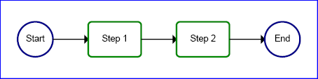
Below is a simple example of the Rendering Custom Content feature. In the example, the SVG file references a set of custom elements for flowcharting using the extensionDefs element, and then uses the custom elements to draw the flowchart. Note that the document below is semantically more meaningful due to the use of the custom elements than it would have been if the file had contained just the low-level visual presentation elements (i.e., circle, rect, path and text):
<svg width="12cm" height="3cm"
     xmlns="http://www.w3.org/2000/svg" version="1.2">
  <desc>Example rcc01 - simple flowchart example using RCC</desc>

  <!-- XPointer reference to the location for the flowchart extensions -->
  <extensionDefs xlink:href="rcc01-flowchart-exts.svg#flowcharts"/>

  <!-- Use the flowchart extensions. As a result of using the extensions,
       a shadow tree of low-level SVG (circle, rect, path elements)
       is added to the SVG DOM. The user agent renders the shadow tree. -->
  <flowchart xmlns="http://example.org/rcc-flowcharts"
             x="0%" y="0%" width="100%" height="100%">
    <terminalNode>Start</terminalNode>
    <processNode>Step 1</processNode>
    <processNode>Step 2</processNode>
    <terminalNode>End</terminalNode>
  </flowchart>
</svg>
View this image as SVG (SVG-enabled browsers only)
Here is the file which defines the simple flowcharting extensions used in the example above:
<svg xmlns="http://www.w3.org/2000/svg" version="1.2"
     xmlns:ev="http://www.w3.org/2001/xml-events">
  <desc>Supplemental file for example rcc01.svg -
        contains definition of simple flowchart extension elements.</desc>

  <extensionDefs id="flowcharts" namespace="http://example.org/rcc-flowcharts">

    <!-- Example needs to be upgraded to show handling of mutation events -->

    <defs>
      <symbol id="connectorline">
        <path transform="translate(0 50)" stroke="black" stroke-width="3" fill="black"
              d="M 0,0 L 90,0 L 90,-10 L 100,0 L 90,10 L 90,0"/>
      </symbol>
    </defs>

    <elementDef name="terminalNode">
      <prototype>
        <g>
          <circle stroke="#008" stroke-width="5"  fill="none" cx="50" cy="50" r="50"/>
          <text x="50" y="57" font-size="25" text-anchor="middle"><refContent/></text>
        </g>
      </prototype>
    </elementDef>

    <elementDef name="processNode">
      <prototype>
        <g>
          <rect stroke="#080" stroke-width="5" fill="none" width="150" height="100" rx="10"/>
          <text x="75" y="57" font-size="25" text-anchor="middle"><refContent/></text>
        </g>
      </prototype>
    </elementDef>

    <elementDef name="flowchart">
      <prototype>
        <svg><refContent/></svg>
      </prototype>
      <handler ev:event="SVGBindEnd" type="text/ecmascript"><![CDATA[
        var svgns = "http://www.w3.org/2000/svg";
        var xlinkns = "http://www.w3.org/1999/xlink";
        var flowchartns = "http://example.org/rcc-flowcharts";
        var ELEMENT_NODE = 1;
        var SIDE_INDENT = 50;
        var PROCESSNODE_WIDTH = 150;
        var TERMINALNODE_WIDTH = 100;
        var CONNECTOR_WIDTH = 100;
        var YPOS = 50;
        var flowchartelement = evt.target;
        var ap = flowchartelement.shadowTree;
        var svgElm = ap.firstChild;
        svgElm.setAttributeNS(null, "x", flowchartelement.getAttribute("x"));
        svgElm.setAttributeNS(null, "y", flowchartelement.getAttribute("y"));
        svgElm.setAttributeNS(null, "width", flowchartelement.getAttribute("width"));
        svgElm.setAttributeNS(null, "height", flowchartelement.getAttribute("height"));

        // Determine total width needed and set viewBox attribute appropriately.
        var totalWidth = 0;
        var nodeCount = 0;
        for( var node = flowchartelement.firstChild ; node != null ; node = node.nextSibling )
        {
          // only process elements in flowchart ns
          if( node.nodeType == ELEMENT_NODE && node.namespaceURI == flowchartns) {
            nodeCount++;
            if (node.localName == "processNode")
              totalWidth += PROCESSNODE_WIDTH;
            else if (node.localName == "terminalNode")
              totalWidth += TERMINALNODE_WIDTH;
          }
        }
        totalWidth += (nodeCount-1)*CONNECTOR_WIDTH + 2*SIDE_INDENT;
        svgElm.setAttributeNS(null, "viewBox", "0 0 "+totalWidth+" 200");
        var xtrans = 50;

        // Position all of the nodes and draw the connectors.
        var xpos = SIDE_INDENT;
        var nodeNum = 0;
        for( var node = flowchartelement.firstChild ; node != null ; node = node.nextSibling )
        {
          // only process elements in flowchart ns
          if( node.nodeType == ELEMENT_NODE && node.namespaceURI == flowchartns) {
            node.shadowTree.setAttributeNS(null, "transform", "translate("+xpos+" "+YPOS+")");
            var nodeWidth;
            if (node.localName == "processNode") {
              nodeWidth = PROCESSNODE_WIDTH;
            } else if (node.localName == "terminalNode") {
              nodeWidth = TERMINALNODE_WIDTH;
            }
            xpos += nodeWidth;
            // Add connector line to end of flowchart node's shadowTree.
            if (nodeNum < (nodeCount-1)) {
              var useElement = document.createElementNS(svgns, "use");
              useElement.setAttributeNS(xlinkns, "xlink:href", "#connectorline");
              useElement.setAttributeNS(null, "transform", "translate("+nodeWidth+" 0)");
              node.shadowTree.appendChild(useElement);
              xpos += CONNECTOR_WIDTH;
            }
            nodeNum++;
          }
        }
      ]]></handler>
    </elementDef>

  </extensionDefs>

</svg>
The next example takes sample code from section 4.6 from the Geography Markup Language (GML) specification, version 2.1.2. The 'extensionDefs' element would effect a client-side transformation from original XML/GML into final-form SVG rendering.
<svg width="12cm" height="3cm"
     xmlns="http://www.w3.org/2000/svg" version="1.2">
  <desc>Example rcc-gml-01 - GML and RCC</desc>

  <!-- XPointer reference to the location for the GML extensions -->
  <extensionDefs xlink:href="rcc-gml-01-exts.svg#gml"/>

  <CityModel xmlns="http://www.opengis.net/examples"
             xmlns:gml="http://www.opengis.net/gml"
             xmlns:xlink="http://www.w3.org/1999/xlink"
             xmlns:xsi="http://www.w3.org/2001/XMLSchema-instance"
             xsi:schemaLocation="http://www.opengis.net/examples city.xsd">

    <gml:name>Cambridge</gml:name>
    <gml:boundedBy>
      <gml:Box srsName="http://www.opengis.net/gml/srs/epsg.xml#4326">
        <gml:coord><gml:X>0.0</gml:X><gml:Y>0.0</gml:Y></gml:coord>
        <gml:coord><gml:X>100.0</gml:X><gml:Y>100.0</gml:Y></gml:coord>
      </gml:Box>
    </gml:boundedBy>

    <cityMember>
      <River>
        <gml:description>The river that runs through Cambridge.</gml:description>
        <gml:name>Cam</gml:name>
        <gml:centerLineOf>
          <gml:LineString srsName="http://www.opengis.net/gml/srs/epsg.xml#4326">
            <gml:coord><gml:X>0</gml:X><gml:Y>50</gml:Y></gml:coord>
            <gml:coord><gml:X>70</gml:X><gml:Y>60</gml:Y></gml:coord>
            <gml:coord><gml:X>100</gml:X><gml:Y>50</gml:Y></gml:coord>
          </gml:LineString>
        </gml:centerLineOf>
      </River>
    </cityMember>

    <dateCreated>2000-11</dateCreated>
  </CityModel>
</svg>
The next example takes sample code from [Appendix G of the XForms specification | http://www.w3.org/TR/xforms/sliceG.html ] . The extensionDefs element would effect a client-side transformation from original XForms elements into final-form SVG rendering. In this example, the assumption is that the extension would implement all or at least a large part of the XForms specification via DOM/scripting.
<svg width="12cm" height="3cm"
     xmlns="http://www.w3.org/2000/svg" version="1.2"
     xmlns:xforms="http://www.w3.org/2002/xforms/cr"
     xmlns:xsd="http://www.w3.org/2001/XMLSchema"
     xmlns:ev="http://www.w3.org/2001/xml-events"
     xmlns:my="http://commerce.example.com/payment">
  <desc>Example rcc-xforms-01 - using RCC within a combined XForms+SVG user agent</desc>
  <title xml:lang="fr">XForms en SVG</title>

  <!-- XPointer reference to the location for the XForms extensions to SVG.
       The extensions convert the XForms UI elements into low-level SVG
       interactive graphics and also provide  high-level features,
       such as client-side validation and the XForms event model. -->
  <extensionDefs xlink:href="rcc-xforms-01-exts.svg#xforms"/>

  <rx:renderXForms xmlns:rx="http://example.org/rcc-xforms"
         xmlns="http://www.w3.org/2002/xforms/cr">

    <model schema="payschema.xsd">
      <instance>
        <my:payment as="credit">
          <my:cc />
          <my:exp />
        </my:payment>
      </instance>
      <submission action="http://www.example.com/buy.rb" method="post" id="s00" />
      <bind nodeset="my:cc" relevant="../@as='credit'" required="true()" />
      <bind nodeset="my:exp" relevant="../@as='credit'" required="true()" />
    </model>

    <group xmlns="http://www.w3.org/2002/xforms/cr">
      <trigger>
        <label>Francais</label>
        <toggle case="fr" ev:event="xforms-activate" />
      </trigger>
      <trigger>
        <label>English</label>
        <toggle case="en" ev:event="xforms-activate" />
      </trigger>
    </group>

    <input ref="my:cc">
      <label xml:lang="fr">Numero de carte bancaire</label>
      <alert xml:lang="fr">Saississez un numro de carte bancaire en cours
       (sparez par un espace ou un trait d'union chaque groupe de chiffres)</alert>
    </input>

    <input ref="my:exp">
      <label xml:lang="fr">Date d'chance</label>
    </input>

    <submit submission="s00">
      <label xml:lang="fr">Achetez</label>
    </submit>
</svg>
The next example supplements the XForms example above with the following simple example which shows a set of extension elements ui:menubar, ui:menu, ui:menuitem) which present a menubar and a scrolling area for graphics.
<svg width="525" height="575"
     xmlns="http://www.w3.org/2000/svg" version="1.2"
     xmlns:ui="http://example.org/rcc-ui">
  <desc>Example rcc-ui-01 - using rcc for UI elements</desc>
  <title>UI in SVG</title>

  <!-- XPointer reference to the location for the UI extensions to SVG.
       The extensions convert the UI elements into low-level SVG. -->
  <extensionDefs xlink:href="rcc-ui-01-exts.svg#ui"/>

  <ui:menubar x="25" y="25" width="500" height="20" font-size="14">
    <ui:menu title=File>
      <ui:menuitem title=New op="newdoc(evt)">
      <ui:menuitem title=Open op="opendoc(evt)">
    </ui:menu>
    <ui:menu title=Edit>
      <ui:menuitem title=Copy op="copy(evt)">
      <ui:menuitem title=Past op="paste(evt)">
    </ui:menu>
  </ui:menubar>

  <ui:scrollArea x="25" y="50" width="500" height="400">
    <image xlink:href="..." ... />
    <path d="..." ... />
    <text transform="..." font-size="...">...</text>
  </ui:scrollArea>
</svg>
The last example shows RCC being used for custom container elements that perform layout, in this case a magazine layout.
<svg>
  ...

  <!-- XPointer reference to the location for the widgets extensions to SVG.
       The extensions convert the widget elements into low-level SVG. -->
  <extensionDefs xlink:href="rcc-dynlayout-01-exts.svg#dynlayout" />

  <foo:DynamicPageLayout>
    <foo:articles>
      <foo:article>
        <foo:title>Major war erupts</foo:title>
        <foo:para>War broke out around the world today...</foo:para>
      </foo:article>
      <foo:article>
        <foo:title>Two headed-chicken born</foo:title>
        <foo:para>The sleepy town of Frostbite Falls is excited about...</foo:para>
      </foo:article>
    </foo:articles>
  </foo:DynamicPageLayout>
  ...
</svg>
4.7 Live Templates: an alternate approach to RCC
Live Templates is the name of an alternate proposal to the Rendering Custom Content feature. The SVG Working Group is currently in the process of reconciling Live Templates with RCC. Some of this has been included above in the RCC section, but the following Live Template details have not been updated. Therefore there will be some inconsistencies in the description below.
The objective of Live Templates is to improve SVG's usability as a front-end for fully interactive Web applications. In classical UI, the data model is in any appropriate XML grammar, the view is SVG, and there is the ability to view (transform the XML to SVG), edit (manipulate the view via DOM or post instructions to a server that would change the XML), and update the view (incrementally change only those parts of the SVG that are affected by changes in the XML, thereby avoiding a complete screen refresh).
There are three main uses of Live Templates:
-
Viewing and editing of an "application data model" stored as XML on
the server - for example the current state of any collaborative
application's data, which must be stored centrally for all to access
and edit.
-
Templating of sub-trees of SVG (i.e. a more general 'use'), which is
achieved by allowing generateContent to refer to a subtree of the
current document as input.
-
Storing and re-styling current user state information rather than
requiring unnecessary visits back to the server (i.e. a "user data
model" as separate from the "application data model"). This is
achieved by using the current state of the DOM for input rather than
the original document.
Refer also to the design objectives and requirements of the RCC, they apply to Live Templates as well.
4.7.1 Overview
Live Templates provides the ability to run a specified XML transformer on a specified XML file or branch of the DOM with specified parameter values, and place the results as a generated SVG sub-tree in a specified location in the SVG. An XML transformer is something that takes XML as input, and produces XML as output, like an XSLT stylesheet.
The newly generated SVG subtree could be placed either directly in the DOM or as a shadow tree accessible as a separate DOM tree by calling a method on the element that generates this shadow tree .
Live Templates also provides ability to re-run the XSLT/XML transformer at any time to replace just the generated results, while leaving the rest of the SVG untouched.
This idea of running a script or other process on an input file to produce a generated SVG sub-tree is not specific to XSLT, or to XML input, so it should be possible, in theory, to specify the MIME type of the script file to be something else like XQuery, Java, or ECMAScript. Let's make XSLT the default and a priority for implementers.
4.7.2 The generateContent element
The generateContent element allows an XML transformer such as an XSLT stylesheet to be run on a specified template XML file or fragment and the results inserted as a shadow tree of the generateContent element. The shadow tree is accessible via a DOM call on the generateContent element.
The generateContent, like the use element, has optional attributes x, y, width and height which are used to map the generated graphical contents onto a rectangular region within the current coordinate system.
Should the 'generateContent' to have similar viewport establishing attributes and behavior as the 'use' element or the 'svg' element?
A DOM method is provided so that script writers may regenerate the shadow tree from template XML at any time. The shadow tree is only generated at two possible times:
-
When the document is initially rendered.
-
When the DOM method to regenerate the tree is called.
A generateContent element has the same visual effect as if the generateContent element was replaced by the shadow tree it generates.
General discussion of shadow tree inheritance, DOM access, and event model should be referenced from here.
We may want to fire an event before the shadow tree is generated and afterwords for script writers. An argument can be made against this, as it encourages doing a lot of rendering "fix-up" in a non-declarative manner with ECMAScript.
-
If the generateContent element references an XML file as input:
The specified XML transformer is run with the XML file as input.
-
If the generateContent element references an element in an
external XML file as input:
The specified XML transformer is run with a constructed document rooted at the referenced element. The DTD of the constructed document is derivable from the DTD of the original document.
-
If the generateContent element references an element in the
current document:
The specified XML transformer is run with a document constructed from the current DOM state, rooted at the referenced element. The DTD of the constructed document is derivable from the DTD of the current document.
This behavior is intended for both templating of SVG itself (a more general 'use') and the ability to store current user state information in an XML model which can be easily transformed to graphics. Separate files would be used for cases in which an external, server-based data model is being maintained
There is an interoperability argument to be made for not allowing this coding style, and enforcing the use of separate files. Keeping custom markup in a separate file would prevent any confusion about what markup is SVG and what markup is custom.
Example Use01 below has a simple 'generateContent' referencing an external template for a simple shape and an XML transformer that creates the SVG for the shape.
<svg width="10cm" height="3cm" viewBox="0 0 100 30" version="1.2"
     xmlns="http://www.w3.org/2000/svg" xmlns:xlink="http://www.w3.org/1999/xlink">

     <generateContent
         x="10" y="10" width="30" height="30"
         transformer="shapes.xsl"
         type="text/xsl"
         input="diamondInstance.xml" />

</svg>
The referenced template file:
diamond xmlns="http://foo.example.org/shapes" />
The referenced XML transformer file:
<xsl:stylesheet version="1.1"
 xmlns="http://www.w3.org/2000/svg"
 xmlns:foo="http://foo.example.org/shapes"
 xmlns:xsl="http://www.w3.org/1999/XSL/Transform">

 <xsl:template match="foo:diamond">

  <rect transform="rotate(44,50%,50%)"
   fill="red"
   width="100%"
   height="100%"/>

 </xsl:template>

</xsl:stylesheet>
The visual effect would be equivalent to the following document:
<svg width="10cm" height="3cm" viewBox="0 0 100 30" version="1.2"
     xmlns="http://www.w3.org/2000/svg" xmlns:xlink="http://www.w3.org/1999/xlink">

     <g transform="translate(10,10)">
         <svg width="30" height="30" >

          <rect transform="rotate(44,50%,50%)"
           fill="red"
           width="100%"
           height="100%"/>

         </svg >
     </g >

</svg>
Example Use02 below has a generateContent referencing an external template for a simple button and an XML transformer that creates the SVG for the button.
<svg width="10cm" height="3cm" viewBox="0 0 100 30" version="1.2"
     xmlns="http://www.w3.org/2000/svg" xmlns:xlink="http://www.w3.org/1999/xlink">

<style type="text/css"<>![CDATA[
      .pushButton {
        fill: green;
        stroke: black;
        stroke-width: 3
      }
    ]]<>/style>

<script type="text/ecmascript"< <![CDATA[

  var angle = 0;

  function myCallback(evt) {

    var document = evt.target.ownerDocument;
    var elem = document.getElementById( "message" )

    // set rotation transform attribute on text.
    angle = angle + 10;
    var transform = "rotate(" + angle + " 100,20 )";
    elem.setAttribute( "transform", transform );
  }

  ]]> </script>


<text id="message" x="20" y="20" font-size="10">Below is a button, please press it</text>

     <generateContent
         x="10" y="10" width="30" height="30"
         transformer="buttons.xsl"
         type="text/xsl"
         input="buttonInstance.xml" />

</svg>
The referenced template file:
<pushButton xmlns="http://bar.example.org/buttons" action="myCallback(evt)"/>
The referenced XML transformer file:
<xsl:stylesheet version="1.1"
        xmlns="http://www.w3.org/2000/svg"
        xmlns:bar="http://bar.example.org/buttons"
        xmlns:xsl="http://www.w3.org/1999/XSL/Transform">

        <xsl:template match="bar:pushButton">

                <xsl:variable name="action" select="./@action"/>

                <g class="pushButton" fill="blue" onclick="{$action}" >

                <rect width="100%" height="100%"/>
                        <svg x="10%" y="10%" width="80%" height="80%">

                                <xsl:apply-templates select="./*"/>

                        </svg>

                </g>
        </xsl:template>
</xsl:stylesheet>
The effect would be equivalent to the following document:
<svg width="10cm" height="3cm" viewBox="0 0 100 30" version="1.2"
     xmlns="http://www.w3.org/2000/svg" xmlns:xlink="http://www.w3.org/1999/xlink">

<style type="text/css"<>![CDATA[
      .pushButton {
        fill: green;
        stroke: black;
        stroke-width: 3
      }
    ]]<>/style>

<script type="text/ecmascript"< <![CDATA[

  var angle = 0;

  function myCallback(evt) {

    var document = evt.target.ownerDocument;
    var elem = document.getElementById( "message" )

    // set rotation transform attribute on text.
    angle = angle + 10;
    var transform = "rotate(" + angle + " 100,20 )";
    elem.setAttribute( "transform", transform );
  }

  ]]> </script>

<text id="message" x="20" y="20" font-size="10">Below is a button, please press it</text>

     <g transform="translate(10,10)">
         <svg width="30" height="30" >

                <g class="pushButton" fill="blue" onclick="myCallback(evt)" >

                <rect width="100%" height="100%"/>
                        <svg x="10%" y="10%" width="80%" height="80%"/>

                </g>

         </svg >
     </g >

</svg>
Example Use03 below has a generateContent combining the two above examples to put the diamond on the button as a label.
<svg width="10cm" height="3cm" viewBox="0 0 100 30" version="1.2"
     xmlns="http://www.w3.org/2000/svg" xmlns:xlink="http://www.w3.org/1999/xlink">

<style type="text/css"<>![CDATA[
      .pushButton {
        fill: green;
        stroke: black;
        stroke-width: 3
      }
    ]]<>/style>

<script type="text/ecmascript"< <![CDATA[

  var angle = 0;

  function myCallback(evt) {

    var document = evt.target.ownerDocument;
    var elem = document.getElementById( "message" )

    // set rotation transform attribute on text.
    angle = angle + 10;
    var transform = "rotate(" + angle + " 100,20 )";
    elem.setAttribute( "transform", transform );
  }

  ]]> </script>

<text id="message" x="20" y="20" font-size="10">Below is a button, please press it</text>

     <generateContent
         x="10" y="10" width="30" height="30"
         transformer="shapesAndButtons.xsl"
         type="text/xsl"
         input="diamondButtonInstance.xml" />

</svg>
The referenced template file:
<bar:pushButton xmlns:bar="http://bar.example.org/buttons"
                action="myCallback(evt)">
        <foo:diamond xmlns:foo="http://foo.example.org/shapes" />
</bar:pushButton>
The referenced XML transformer file:
<xsl:stylesheet version="1.1"
        xmlns:xsl="http://www.w3.org/1999/XSL/Transform">

        <xsl:import href="buttons.xsl"/>
        <xsl:import href="shapes.xsl"/>

</xsl:stylesheet>
The effect would be equivalent to the following document:
<svg width="10cm" height="3cm" viewBox="0 0 100 30" version="1.2"
     xmlns="http://www.w3.org/2000/svg" xmlns:xlink="http://www.w3.org/1999/xlink">

<style type="text/css"<>![CDATA[
      .pushButton {
        fill: green;
        stroke: black;
        stroke-width: 3
      }
    ]]<>/style>

<script type="text/ecmascript"< <![CDATA[

  var angle = 0;

  function myCallback(evt) {

    var document = evt.target.ownerDocument;
    var elem = document.getElementById( "message" )

    // set rotation transform attribute on text.
    angle = angle + 10;
    var transform = "rotate(" + angle + " 100,20 )";
    elem.setAttribute( "transform", transform );
  }

  ]]> </script>

<text id="message" x="20" y="20" font-size="10">Below is a button, please press it</text>

     <g transform="translate(10,10)">
         <svg width="30" height="30" >

                <g class="pushButton" fill="blue" onclick="myCallback(evt)" >

                <rect width="100%" height="100%"/>
                        <svg x="10%" y="10%" width="80%" height="80%">
                            <rect transform="rotate(44,50%,50%)"
                             fill="red"
                             width="100%"
                             height="100%"/>

                        </svg >
                </g>

         </svg >
     </g >
</svg>
Example Use04 below has a generateContent transformer and input xml in the same file.
<svg width="10cm" height="3cm" viewBox="0 0 100 30" version="1.2"
     xmlns="http://www.w3.org/2000/svg" xmlns:xlink="http://www.w3.org/1999/xlink">

<script id="diamond" type="text/xsl"<
  <xsl:stylesheet version="1.1"
   xmlns="http://www.w3.org/2000/svg"
   xmlns:foo="http://foo.example.org/shapes"
   xmlns:xsl="http://www.w3.org/1999/XSL/Transform">

   <xsl:template match="foo:diamond">

    <rect transform="rotate(44,50%,50%)"
     fill="red"
     width="100%"
     height="100%"/>

   </xsl:template>

  </xsl:stylesheet>
</script>

     <generateContent
         x="10" y="10" width="30" height="30"
         transformer="#diamond"
         type="text/xsl"
         input="#diamondInstance" />

<metadata>
  <diamond id="diamondInstance" xmlns="http://foo.example.org/shapes" />
</metadata>

</svg>
Example Use05 below has a generateContent referencing an XML transformer that allows binding SVG events to generated content.
The referenced template file:
<foo:teleportCircle
        xmlns="http://www.w3.org/2000/svg"
        xmlns:foo="http://foo.example.org/teleport"

        foo:url="http://www.w3c.org"
        cx="100" cy="100" r="30" fill="red" onmouseover="myCallback(evt)">
</foo:teleportCircle>
The referenced XML transformer file:
<xsl:stylesheet version="1.1"
        xmlns="http://www.w3.org/2000/svg"
        xmlns:xlink="http://www.w3.org/1999/xlink"
        xmlns:foo="http://foo.example.org/teleport"
        xmlns:xsl="http://www.w3.org/1999/XSL/Transform">

        <xsl:template match="foo:teleportCircle">

                <xsl:variable name="url" select="./@foo:url"/>

                <a xlink:href="{$url}">
                        <circle>
                                <xsl:for-each select="./@*[name() != 'onclick' and name() != 'foo:url']">
                                        <xsl:variable name="attrName" select="name()"/>
                                        <xsl:attribute name="{$attrName}"><xsl:value-of select="."/></xsl:attribute>
                                </xsl:for-each>
                        </circle>
                </a>

        </xsl:template>

</xsl:stylesheet>
The effect would be equivalent to the following document:
<svg width="10cm" height="3cm" viewBox="0 0 100 30" version="1.2"
     xmlns="http://www.w3.org/2000/svg" xmlns:xlink="http://www.w3.org/1999/xlink">

<style type="text/css"><![CDATA[
      .pushButton {
        fill: green;
        stroke: black;
        stroke-width: 3
      }
    ]]></style>

<script type="text/ecmascript"> <![CDATA[

  var angle = 0;

  function myCallback(evt) {

    var document = evt.target.ownerDocument;
    var elem = document.getElementById( "message" )

    // set rotation transform attribute on text.
    angle = angle + 10;
    var transform = "rotate(" + angle + " 100,20 )";
    elem.setAttribute( "transform", transform );
  }

  ]]> </script>

<text id="message" x="20" y="20" font-size="10">Below is a teleporter</text>

<a xlink:href="http://www.w3c.org">
        <circle cx="100" cy="100" r="30" fill="red" onmouseover="myCallback(evt)"/>
</a>

</svg>
TODO: a DTD or schema fragment.
Attribute definitions:
-
x = " <coordinate>"
-
The x-axis coordinate of one corner of the
rectangular region into which the shadow tree placed. If the
attribute is not specified, the effect is as if a value of "0" were
specified. Animatable : yes.
-
y = " <coordinate>"
-
The y-axis coordinate of one corner of the
rectangular region into which the shadow tree is placed. If the
attribute is not specified, the effect is as if a value of "0" were
specified. Animatable : yes.
-
width = " <length>"
-
The width of the rectangular region into which
the shadow tree is placed. A negative value is an error (see Error
processing ). A value of zero disables rendering of this element.
Animatable : yes.
-
height = " <length>"
-
The height of the rectangular region into
which the shadow tree is placed. A negative value is an error (see
Error processing ). A value of zero disables rendering of this
element. Animatable : yes.
-
transformer = " <uri>"
-
A URI reference to an XML transformer, such
as an XSLT stylesheet. Animatable : no.
-
type = "content-type"
-
Identifies the XML transformer language for
the given 'generateContent' element. The value content-type
specifies a media type, per [ RFC2045 ]. Animatable : no.
-
input = "(uri))"
-
A URI reference to an XML input document or
element/fragment within an XML document. Animatable : no.
4.7.3 The param element
The param element passes string information to the XML transformer (such as XSLT), mimicking the information that could be passed on the command line to the XML transformer.
Example Use06 below has two generateContent elements that use the 'param' element to pass parameters to the XML transformer.
<svg width="10cm" height="10cm" viewBox="0 0 100 100" version="1.2"
     xmlns="http://www.w3.org/2000/svg" xmlns:xlink="http://www.w3.org/1999/xlink">

<style type="text/css"><![CDATA[
      .pushButton {
        fill: green;
        stroke: black;
        stroke-width: 3
      }
    ]]></style>

<script type="text/ecmascript"> <![CDATA[

  var angle = 0;

  function rotatePlus(evt) {

    var document = evt.target.ownerDocument;
    var elem = document.getElementById( "message" )

    // set rotation transform attribute on text.
    angle = angle + 10;
    var transform = "rotate(" + angle + " 100,20 )";
    elem.setAttribute( "transform", transform );
  }

  function rotateMinus(evt) {

    var document = evt.target.ownerDocument;
    var elem = document.getElementById( "message" )

    // set rotation transform attribute on text.
    angle = angle - 10;
    var transform = "rotate(" + angle + " 100,20 )";
    elem.setAttribute( "transform", transform );
  }

  ]]> </script>

<text id="message" x="20" y="20" font-size="10">Below are buttons, please press them</text>

        <generateContent
                x="10" y="100" height="30" width="30"
                type="text/xsl" input="paramButtonInstance.xml" transformer="paramButtons.xsl">
                <param name="action" value="rotatePlus(evt)"/>
        </generateContent>

        <generateContent
                x="100" y="100" height="30" width="30"
                type="text/xsl" input="paramButtonInstance.xml" transformer="paramButtons.xsl">
                <param name="action" value="rotateMinus(evt)"/>
        </generateContent>

</svg>
The referenced template file:
<pushButton xmlns="http://bar.example.org/buttons" fill="blue"/>
The referenced XML transformer file:
<xsl:stylesheet version="1.1"
        xmlns="http://www.w3.org/2000/svg"
        xmlns:bar="http://bar.example.org/buttons"
        xmlns:xsl="http://www.w3.org/1999/XSL/Transform">

        <xsl:param name="action" />

        <xsl:template match="bar:pushButton">


                <xsl:variable name="fill" select="./@fill"/>

                <g class="pushButton" fill="blue" onclick="{$action}" >

                        <rect width="100%" height="100%"/>
                        <svg width="100%" height="100%" viewBox="0 0 100 100">

                                <xsl:apply-templates select="./*"/>

                        </svg>

                </g>

        </xsl:template>

</xsl:stylesheet>
The effect would be equivalent to the following document:
<svg width="10cm" height="10cm" viewBox="0 0 100 100" version="1.2"
     xmlns="http://www.w3.org/2000/svg" xmlns:xlink="http://www.w3.org/1999/xlink">

<style type="text/css"><![CDATA[
      .pushButton {
        fill: green;
        stroke: black;
        stroke-width: 3
      }
    ]]></style>


<script type="text/ecmascript"> <![CDATA[

  var angle = 0;

  function rotatePlus(evt) {

    var document = evt.target.ownerDocument;
    var elem = document.getElementById( "message" )

    // set rotation transform attribute on text.
    angle = angle + 10;
    var transform = "rotate(" + angle + " 100,20 )";
    elem.setAttribute( "transform", transform );
  }

  function rotateMinus(evt) {

    var document = evt.target.ownerDocument;
    var elem = document.getElementById( "message" )

    // set rotation transform attribute on text.
    angle = angle - 10;
    var transform = "rotate(" + angle + " 100,20 )";
    elem.setAttribute( "transform", transform );
  }

  ]]> </script>

<text id="message" x="20" y="20" font-size="10">Below are buttons, please press them</text>

     <g transform="translate(10,100)">
         <svg width="30" height="30" >

         <g class="pushButton" fill="blue" onclick="rotatePlus(evt)">
                <rect width="100%" height="100%"/>
         </g>

         </svg>
     </g>

     <g transform="translate(100,100)">
         <svg width="30" height="30" >

         <g class="pushButton" fill="blue" onclick="rotateMinus(evt)">
                <rect width="100%" height="100%"/>
         </g>

         </svg>
     </g>

</svg>
TODO: Schema or DTD fragment
Attribute definitions:
-
value = " <string>"
-
The string value of the parameter for the XML
transformer. Animatable : no.
-
name = " <string>"
-
The name of the parameter for the XML
transformer, if the XML transformer (like XSLT) has named
parameters/flags. Animatable : no.
4.7.4 DOM Interfaces
The following interfaces will be defined below: GenerateContentElement and ParamsElement.
These interfaces are not yet ready.
For the GenerateContentElement interface, the important methods to define are:
-
Method that causes the shadow tree to be re-generated by invoking
the XML transformer again
-
Method for getting access to the generated shadow tree
5 Enhancements for User Interface development
XForms is a technology for describing forms in XML. It separates the model, or the information that is to be sent as the result of the form, from the abstract controls that will be used to get information from the person using the form. XForms deliberately says nothing about presentation of form controls; this is left to a styling or transformation language, to generate the actual visual (or indeed, audio) form widgets. XForms cannot be used by itself; it is designed to be integrated into a host language, such as SVG. This provides the host language with an abstract definition of form content and leaves the rendering to the host. SVG is well suited to hosting XForms, since it provides powerful rendering and interactivity APIs.
Furthermore, a generic set of user interface components has been a common request from the SVG community. By describing how SVG and XForms can be integrated that request can be answered while providing more functionality if required. For example, the tight integration with a data model of a form should allow an SVG/XForms implementation to package SOAP messages easily. It also would allow an author to provide multiple interfaces to the same form (SVG, CSS, VoiceXML).
It also should be possible to extend generic form controls to use an SVG rendering specified by the document author. Events within the SVG rendering should be linked to behavior that updates the form model.
At the time of publication, the Working Group is undecided as to whether or not the SVG specification should describe a default rendering and behavior for some form elements, such as buttons and sliders. We realize that creating widget sets is a deep topic and specifically request feedback on this matter. Would a simple set of form widgets be sufficient in most situations, or would authors prefer to always create the SVG rendering and behavior for every element?
Readers will notice the RCC section makes a number of references to XForms. The current feeling of the Working Group is enable XForms through this feature and by adding a small number of low-level widgets to the SVG language (such as text-entry).
5.2 Element focus and navigation
In many cases, such as text editing, the user is required to place focus on a particular element, ensuring that input events, such as keyboard input, are sent to that element.
-
focusable
-
| Value: |
"true" | "false" | "auto"
|
| Initial: |
"auto"
|
| Applies to: |
container elements and graphics elements
|
| Inherited: |
no
|
| Percentages: |
N/A
|
| Media: |
visual
|
| Animatable: |
yes
|
The focusable property determines if an element can get keyboard focus (i.e. receive keyboard events) and participate in the "tab order". The value "true" means that the element is keyboard-aware and should be treated as any other UI component that can get focus. The value "false" means that it should not. The value "auto" is equivalent to "false", except that it acts like "true" for the following cases:
-
the a element
-
the text and flowDiv elements with editable set to "true"
-
the top-level svg element
The following open issues are yet to be discussed:
-
API to get focus? (SVGElement::focus() or special interface)
-
Can SVGElemenInstance get focus (elements referenced by use element)? Answer
is probably yes.
-
Should every instance get its own tab stop? Answer is probably yes.
-
Changing the tab order? (cancel the Tab keyboard event and call focus())
The SVG 1.1 language does not specify a method for the declarative display of tooltips on SVG content. While it suggests that the content of the title element could be displayed as a tooltip, it does not provide any control for the content developer. This meant that developers resorted to implementing their own tooltip functionality using scripting.
SVG 1.2 adds declarative tooltip support through the tooltip property. This allows for the display of textual tooltips to be declaratively controlled for each element in the SVG document. User agents should use the platform tooltip system if there is one available. On platforms without native support for tooltips, user agents can implement their own tooltip system. This means that the appearance, position and behavior of the tooltip is implementation or platform specific.
However, in the visual environment, the user agent must attempt to display the entire tooltip in a readable manner, avoiding clipping by the edge of the device or canvas. If possible the tooltip should be implemented as a temporary graphic that is superimposed on the top of the SVG canvas at the location of the pointer if one exists. Also, if possible, the content of the tooltips should be made available to accessibility implementations on the device.
The SVG Working Group plans to add a feature to provide enhanced floating windows above the canvas, which would allow for more graphically rich tooltips. This may not be tied to the tooltip property, which provides the common functionality. That is, rich floating graphics are not considered tooltips for now.
5.3.1 The hint element
The hint element is another level of metadata for an element. The contents of the hint element are intended to be displayed by a tooltip. It differs from the title and desc elements in that a hint may give instructions to the user, as opposed to describe the element that it belongs to.
<svg xmlns="http://www.w3.org/2000/svg" version="1.2">

  <circle cx="50" cy="50" r="25" fill="red" tooltip="enable">
    <title>The target area</title>
    <hint>Click here to start the animation</hint>
    <animate .... />
  </circle>

</svg>
The following is an extract of the schema that describes the hint element:
<xs:element name="hint">
  <xs:complexType mixed="true">
    <!-- any attributes? -->
  </xs:complexType>
</xs:element>
The tooltip property specifies whether or not tooltips should be displayed for this element.
-
tooltip
-
| Value: |
enable | disable | inherit
|
| Initial: |
enable
|
| Applies to: |
graphics and container elements
|
| Inherited: |
yes
|
| Percentages: |
N/A
|
| Media: |
visual
|
| Animatable: |
yes
|
If the tooltip property is set to "enable" then the content of the tooltip is the text content of the hint child of an element. For elements that do not have a hint child, the tooltip content is the content of its parent's tooltip. If the tooltip property is set to "disable" then the content of the tooltip is empty. The value of the tooltip for a root svg element without a hint child is empty. In the case of an empty value, the tooltip will not be displayed.
Tooltips and the CSS hover property both track the mouseover and mouseout events. Tooltips may require the pointer to be stationary over the target for a short period of time. Tooltips and hover represent additive effects. The hover processing should occur first followed by tooltip processing. That is, tooltip processing is placed after hover processing and before hyperlink processing. Tooltips respond to pointer events in the same manner as hover, thus do not activate on elements with either the display or pointer-events properties set to "none".
6 XML Events Integration
6.1 The handler element
The handler element is similar to the script element: its contents, either included inline or referenced, are code that is to be executed by the scripting engine(s) used by user agent.
However, where the script element evaluates its contents when the document is loaded, the handler element evaluates its contents in response to a event. This makes handler functionally equivalent to using the event attributes.
For example, consider the following SVG 1.1 document:
<svg xmlns="http://www.w3.org/2000/svg" version="1.1">

  <rect id="myRect" x="10" y="20" width="200" height="300" fill="red"
     onclick="var width =  parseFloat(
                  document.getElementById('myRect').getAttribute('width'));
              document.setAttribute('myRect', 'width', (width+10));"/>

</svg>
The above example can be rewritten to use the handler element and XML Events (described below) as shown:
<svg xmlns="http://www.w3.org/2000/svg" version="1.2"
     xmlns:ev="http://www.w3.org/2001/xml-events">

  <rect id="myRect" x="10" y="20" width="200" height="300" fill="red">

    <handler type="text/ecmascript" ev:event="click">
        var myRect = evt.target;
        var width = parseFloat(myRect.getAttribute("width"));
        myRect.setAttribute("width", (width+10));
    </handler>

  </rect>

</svg>
In ECMAScript, the contents of the handler element behave as if they are the contents of a new function object, created as shown:
function(evt) {
  // contents of handler
}
Other interpreted languages behave in as similar a manner as possible.
The 'evt' parameter shown above is an Event object corresponding to the event that has triggered the handler.
The following is a schema extract which defines the handler element:
<xs:element name="handler">
  <xs:complexType>
    <xs:attributeGroup ref="commonAttrs"/>
    <xs:attribute name="type" use="required"/>
    <xs:attribute ref="xlink:href"/>
    <xs:attribute ref="xml:base"/>
    <xs:attribute ref="ev:event"/>
  </xs:complexType>
</xs:element>
Attributes:
-
type = "content-type":
-
Identifies the language used for the handler element. The value specifies
a media type, per RFC2045. Animatable: no.
-
xlink:href:
-
If this attribute is present, then the script content of the handler
element should be loaded from this resource. Animatable: no.
-
xml:base:
-
If this attribute is present, then it should be used as the base URI
for the xlink:href attribute. Animatable: no.
-
ev:event:
-
The name of the event to handle.
For compiled languages, the xlink:href and xml:base attributes have the same meaning as the classid and codebase attributes in HTML 4.01. The reference must resolve to a class that implements the XMLEventHandler interface (described below).
6.1.1 Parameters to handler elements
In many situations, the script author uses the handler as a template for calling other functions, using the content of the handler element to pass parameters. However, for compiled languages the handler element does not have any executable content.
In this case, the author should embed the parameters into the handler as custom content. The execution of the handler code retrieves the contents of the parameters using the DOM.
Below is an example of using parameters on the handler element:
<svg xmlns="http://www.w3.org/2000/svg" version="1.2"
     xmlns:ev="http://www.w3.org/2001/xml-events"
     xmlns:foo="http://www.example.com/foo">

  <rect id="myRect" x="10" y="20" width="200" height="300"
        fill="red"/>

  <!-- register a listener for a myRect.click event -->
  <ev:listener ev:event="click" ev:observer="myRect"
               ev:handler="#myClickHandler" />

  <handler id="myClickHandler" type="application/java"
           xml:base="http://example.com/myJar.jar"
           xlink:href="#com.example.MyXMLEventHandler"/>
      <foo:offset value="10"/>
      <foo:person>
         <foo:name>Victor Vector</foo:name>
         <foo:age>42</foo:age>
      </foo:person>
  </handler>

</svg>
In this case, the object com.example.MyXMLEventHandler has its handleEvent method called whenever a 'click' event on the 'myRect' object is observed. The object can then retrieve the children of the handler element in order to obtain the contents of the elements from the "foo" namespace.
6.2 XML Events
XML Events is an XML syntax for integrating event listeners and handlers with DOM Event interfaces. Declarative event handling in SVG 1.1 is hardwired into the language, in that the developer is required to embed the event handler in the element syntax (e.g. an element has an onclick attribute). SVG 1.2 adds support for XML Events, providing the ability to listen to custom events, as well as specifying the event listener separately from the graphical content.
The following is an example of an SVG file using XML Events:
<svg xmlns="http://www.w3.org/2000/svg" version="1.2"
     xmlns:ev="http://www.w3.org/2001/xml-events">

  <rect id="myRect" x="10" y="20" width="200" height="300"
        fill="red"/>

  <!-- register a listener for a myRect.click event -->
  <ev:listener ev:event="click" ev:observer="myRect"
               ev:handler="#myClickHandler" />

  <handler id="myClickHandler" type="text/ecmascript">
    var myRect = document.getElementById("myRect");
    var width = parseFloat(myRect.getAttribute("width"));
    myRect.setAttribute("width", (width+10));
  </handler>

</svg>
In the above example, the ev:listener element registers that the myClickHandler element should be invoked whenever a "click" event happens on "myRect".
The handler element has been added to SVG 1.2 and is described in the following section.
The combination of the XML Events syntax and the new handler element allows event handling to be more easily processed in a compiled language. Below is an example of an event handler using the Java language:
<svg xmlns="http://www.w3.org/2000/svg" version="1.2"
     xmlns:ev="http://www.w3.org/2001/xml-events">

  <rect id="myRect" x="10" y="20" width="200" height="300"
        fill="red"/>

  <!-- register a listener for a myRect.click event -->
  <ev:listener ev:event="click" ev:observer="myRect"
               ev:handler="#myClickHandler" />

  <handler id="myClickHandler" type="application/java"
           xml:base="http://example.com/myJar.jar"
           xlink:href="#com.example.MyXMLEventHandler"/>
      <param name="offset" value="10"/>
  </handler>

</svg>
In this case, the handler element specifies the location of compiled code that conforms to the XMLEventHandler interface. The user agent invokes the handleEvent method within the targeted interface.
In this case, the MyXMLEventHandler has the following definition:
package com.example;

import org.w3c.xyz.XMLEventHandler;
import org.w3c.dom.Document;
import org.w3c.dom.Element;
import org.w3c.dom.events.Event;

public class MyXMLEventHandler implements XMLEventHandler {

  Document document;

  public void init(Document doc, Element handlerElement) {
    document = doc;
    // ...
  }

  public void handleEvent(Event event) {
    Element myRect = document.getElementById("myRect");
    float width = Float.parseFloat(myRect.getAttribute("width"));
    myRect.setAttribute(width, "" + (width + 10));
  }
}
The XMLEventHandler interface needs to be developed within the W3C. Notice the "org.w3c.xyz" prefix on the Interface name. The SVG Working Group will liase with the HTML Working Group to provide an interface for this class.
The definition of the XMLEventHandler Interface is shown below:
 /**
 * XMLEventHandler
 */
 interface XMLEventHandler extends org.w3c.dom.events.EventHandler {

  /**
   * Gives the handler an opportunity to do any type of
   * initialization it requires.
   * This should be called before the onload event is
   * dispatched on the Document.
   *
   * @param doc reference to the Document this handler is
   *        attached to
   * @param handler reference to the handler element
   */
  void init(in Document doc, in Element handler);
 }
SVG 1.0 used SMIL Animation for its animation syntax. It has been a common request from the public to have more features from SMIL in SVG. For that reason, SVG 1.2 will mostly likely incorporate more of SMIL 2.0. In this document the audio, video and some timing elements are described. Future revisions will expand on the SMIL integration.
The current proposal is to add more SMIL elements into the SVG language. Alternatively, the SVG Working Group may produce a W3C Note which defines an SVG+SMIL profile, similar to the XHTML+SMIL profile.
It is worth noting what parts of SMIL 2.0 are not under consideration for SVG 1.2. SVG would probably not include SMIL Layout, Linking, Structure and MetaInformation.
7.1 The audio element
The audio element specifies an audio file which is to be rendered to provide synchronized audio. The usual SMIL animation features are used to start and stop the audio at the appropriate times. An xlink:href is used to link to the audio content. No visual representation is produced. However, content authors can if desired create graphical representations of control panels to start, stop, pause, rewind, or adjust the volume of audio content.
It is an open question what audio formats, if any, would be required for conformance. For the image element, SVG mandates support of PNG, JPEG and SVG formats and allows others. All three mandatory formats may be implemented without royalty payments. Many common audio formats, such as MP3, require payment of royalties. One option under consideration is the Vorbis audio compression in the Ogg format. Ogg/Vorbis audio files are believed to be implementable without royalty payments. Another option is to say that there are no required formats, and each implementation supports whatever format the operating system provides. Clearly, this would lead to non-interoperable, platform-dependent content.
The following is a extract of an XML Schema that describes the audio element.
<xs:element name="audio">
  <xs:complexType>
    <xs:complexContent>
      <xs:restriction base="xsd:anyType">
    </xs:restriction>
    <xs:attributeGroup ref="XLinkEmbedAttrs"/>
    <xs:attributeGroup ref="MediaAttrs"/>
  </xs:complexType>
</xs:element>
The following example illustrates the use of the audio element. When the button is pushed, the audio file is played three times.
<svg width="100%" height="100%" version="1.2"
     xmlns="http://www.w3.org/2000/svg"
     xmlns:xlink="http://www.w3.org/1999/xlink">

  <desc>SVG audio example</desc>

  <audio xlink:href="ouch.ogg" volume="0.7" type="audio/vorbis"
        begin="mybutton.click" repeatCount="3"/>

  <g id="mybutton">
    <rect width="150" height="50" x="20" y="20" rx="10"
      fill="#ffd" stroke="#933" stroke-width="5"/>
    <text x="95" y="55" text-anchor="middle" font-size="30"
      fill="#933">Press Me</text>
  </g>

  <rect x="0" y="0" width="190" height="90" fill="none" stroke="#777"/>

</svg>
When rendered, this looks as follows:

The DOM interface for the audio element is shown below:
interface SVGAudioElement :
                SVGAnimationElement,
                SVGURIReference,
                SVGLangSpace {

    readonly attribute SVGAudio audio;
};
7.2 The video element
The video element specifies a video file which is to be rendered to provide synchronized video. The usual SMIL animation features are used to start and stop the video at the appropriate times. An xlink:href is used to link to the video content. It is assumed that the video content also includes an audio stream, since this is the usual way that video content is produced, and thus the audio is controlled by the video element's media attributes.
The video element produces a rendered result, and thus has width, height, x and y attributes.
It is an open question what video formats, if any, would be required for conformance. For the image element, SVG mandates support of PNG, JPEG and SVG formats and allows others. All three mandatory formats may be implemented without royalty payments. Many common video formats, such as RealVideo, Quicktime movies or Windows media Format video, require payment of royalties for most common codecs. W3C would be interested in suggestions for a royalty-free video format that could be used in any free or commercial SVG implementation without royalty.
The following is a extract of an XML Schema that describes the video element.
<xs:element name="video">
  <xs:complexType>
    <xs:complexContent>
      <xs:restriction base="xsd:anyType">
    </xs:restriction>
    <xs:attribute name="x"/>
    <xs:attribute name="y"/>
    <xs:attribute name="width"/>
    <xs:attribute name="height"/>
    <xs:attribute name="preserveAspectRatio"/>
    <xs:attributeGroup ref="PresentationAttrs"/>
    <xs:attributeGroup ref="StyleAttrs"/>
    <xs:attributeGroup ref="XLinkEmbedAttrs"/>
    <xs:attributeGroup ref="MediaAttrs"/>
  </xs:complexType>
</xs:element>
The following example illustrates the use of the video element. The video content is partially obscured by other graphics elements. Experiments within the SVG working group have shown that adequate performance can be obtained by rendering the video in an offscreen buffer and then transforming and compositing it in the normal way, so that it behaves like any other graphical primitive such as an image or a rectangle. It may be scaled, rotated, skewed, displayed at various sizes, and animated.
<svg xmlns="http://www.w3.org/2000/svg" version="1.2"
     xmlns:xlink="http://www.w3.org/1999/xlink"
     width="420" height="340" viewBox="0 0 420 340">
  <desc>SVG 1.2 video example</desc>
    <g>
    <circle cx="0" cy="0" r="170" fill="#da4" fill-opacity="0.3"/>
    <video xlink:href="noonoo.avi" volume=".8" type="video/x-msvideo"
         width="320" height="240" x="50" y="50" repeatCount="indefinite"/>
    <circle cx="420" cy="340" r="170" fill="#927" fill-opacity="0.3"/>
    <rect x="1" y="1" width="418" height="338" fill="none"
       stroke="#777" stroke-width="1"/>
    </g>
</svg>
Show this example of the video element (requires an SVG 1.2 viewer and support for a Windows AVI using Motion JPEG. This is a 3.7M video file).
When rendered, this looks as follows:
The DOM interface for the video element is shown below:
interface SVGVideoElement :
                SVGAnimationElement,
                SVGURIReference,
                SVGLangSpace,
                SVGStylable,
                SVGTransformable {
  readonly attribute SVGAnimatedLength x;
  readonly attribute SVGAnimatedLength y;
  readonly attribute SVGAnimatedLength width;
  readonly attribute SVGAnimatedLength height;
  readonly attribute SVGAnimatedPreserveAspectRatio preserveAspectRatio;

  // a reference to the media stream interface
  readonly attribute SVGVideo video;
};
The audio and video elements described above both refer to a set of media attributes. For SVG 1.2 this set includes a single property, audio-level.
-
audio-level
-
| Value: |
<float>
|
| Initial: |
1
|
| Applies to: |
audio, video and container elements
|
| Inherited: |
no
|
| Percentages: |
N/A
|
| Media: |
visual
|
| Animatable: |
yes
|
The audio-level property specifies a value between 0 and 1 that is used to calculate the volume of a particular element. Values above 1 and below 0 are clipped.
An element's volume is the product of its audio-level property and the element volume of its parent. The exception to this rule is the root element, where the element volume is only the value of its audio-level property. Therefore, element volume is calculated in a similar way to opacity.
This means that if you set the audio-level of an element to a value less than 1.0, all children elements will be quieter. It is not possible to increase the volume on an element.
The output signal level is calculated using the logarithmic scale described below (where vol is the value of the element volume):
dB change in signal level = 20 * log10(vol)
If the element has an element volume of 0, then the output signal will be inaudible. If the element has an element volume of 1, then the output signal will be at the system volume level. Neither the audio-level property or the element volume override the system volume setting.
7.4 Transition effects
There exist a number of usage scenarios for transition effects between views of SVG. For example, an image slideshow or multipage SVG documents.
SMIL 2.0 defines syntax for allowing the transition between multimedia elements to include a transition, such as a fadein/fadeout. There is a comprehensive set of transition effects defined by SMPTE and listed in an appendix of SMIL 2.0 Transition Effects
SVG 1.2 adds the transition effects from SMIL 2.0, in particular the transition element and the transIn and transOut attributes.
7.4.1 The transition element
The transition element defines a single transition class. A transition element can be the child of any class, although normally they are defined within a defs section.
The following is an extract of an XML Schema that describes the transition element:
<xs:element name="transition">
  <xs:complexType>
    <xs:attribute name="type" use="required"/>
    <xs:attribute name="subtype"/>
    <xs:attribute name="dur"/>
    <xs:attribute name="startProgress"/>
    <xs:attribute name="endProgress"/>
    <xs:attribute name="direction"/>
    <xs:attribute name="fadeColor"/>
  </xs:complexType>
</xs:element>
Attributes:
-
type
-
The type of transition. This attribute is required and must be
one of the transition families listed in the
SMIL 2.0 Transitions Taxonomy.
-
subtype
-
The subtype of the transition. If specified then the attribute must be
a recognized subtype of the transition type. If not specified, then
the subtype is the default for the particular transition type.
-
dur
-
The duration of the transition. If specified it must be a
clock-value. The default value is "1s".
-
startProgress
-
This is the amount of progress through the transition at which to
begin execution. Legal values are real numbers in the range
0.0-1.0. For instance, we may want to begin a crossfade with the
destination image being already 30% faded in. For this case,
startProgress would be 0.3. The default value is 0.0.
-
endProgress
-
This is the amount of progress through the transition at which to
end execution. Legal values are real numbers in the range 0.0-1.0
and the value of this attribute must be greater than or equal to the
value of the startProgress attribute. If endProgress is equal to
startProgress, then the transition remains at a fixed progress for
the duration of the transition. The default value is 1.0.
-
direction
-
This specifies the direction the transition will run. The legal
values are "forward" and "reverse". The default value is
"forward". Note that this does not impact the media being
transitioned to, but only affects the geometry of the
transition. For instance, if you specified a type of "barWipe" and a
subtype of "leftToRight", then the media would be wiped in by a
vertical bar moving left to right. However, if you specified
direction="reverse", then it would be wiped in by the same vertical
bar moving right to left. Another example is the type of "starWipe"
and subtype of "fourPoint". For this transition, running the
transition forward reveals the destination media on the inside of a
four-point star which starts small and gets larger as the transition
progresses. Running this transition in reverse would reveal the
destination media in the area outside of a large four-point
star. The star begins large and gets smaller as the transition
progresses. Note that not all transitions will have meaningful
reverse interpretations. For instance, a crossfade is not a
geometric transition, and therefore has no interpretation of reverse
direction. Transitions which do not have a reverse interpretation
should ignore the direction attribute and assume the default value
of "forward".
-
fadeColor
-
If the value of the "type" attribute is "fade" and the value of the
"subtype" attribute is "fadeToColor" or "fadeFromColor", then this
attribute specifies the starting or ending color of the fade. If the
value of the "type" attribute is not "fade", or the value of the
"subtype" attribute is not "fadeToColor" or "fadeFromColor", then
this attribute is ignored. The allowed values are any color
value or a reference to a solidColor object. The default value
is "black".
None of the attributes on the transition element are animatable.
SVG 1.2 does not allow extensions to the transition types specified by SMIL 2.0.
7.4.2 The transition attributes
Once a transition has been defined in a document, then an transition effect is applied by referencing the transition from the transIn and transOut attributes. The transition attributes are added to the elements that can undergo a transition (listed below).
Transitions specified with a transIn attribute will begin at the beginning of the animation's active duration. Transitions specified with a transOut attribute will end at the end of the animation's active duration or end at the end of the element's fill state if a non-default fill value is applied.
Note that in SVG, the transition effects only apply to animations modifying the xlink:href attribute of graphical elements: image, video, use and feImage.
Transitions will most likely also apply to display of page elements, but this is yet to be defined.
The value of the attributes is a semicolon-separated list of transition element identifiers. The transition used is the first supported transition in the list.
Below is an example of a transition:
<svg width="100%" height="100%" version="1.2"
     xmlns="http://www.w3.org/2000/svg"
     xmlns:xlink="http://www.w3.org/1999/xlink">

  <defs>
    <transition id="fadeToRed2s" type="fade" subtype="fadeToColor"
                fadeColor="red" dur="2s"/>
    <transition id="fadeFromRed1s" type="fade" subtype="fadeFromColor"
                fadeColor="red" dur="1s"/>
  </defs>

  <image x="0" y="0" width="100" height="100"
         transIn="fadeFromRed1s"
         transOut="fadeToRed2s">

    <animate attributeType="XML"
             attributeName="xlink:href"
             begin="0s"
             dur="60s"
             values="1.jpg;2.jpg;3.jpg;4.jpg"
             fill="freeze"/>

  </image>

</svg>
7.5 Timing and Synchronization
The SMIL2 Timing and Synchronization module allows for simpler authoring of multimedia content with multiple elements. SVG 1.2 plans to add the par and seq elements in order to create synchronized presentations.
There are a number of attributes that should be added to SVG 1.2 in order to control the synchronization of timed content. These include syncBehavior, syncTolerance, syncMaster, timeContainer, and timeAction as well as expanding the range of allowed fill attribute values.
SVG 1.2 also plans to allow timed content, such as animations, to begin before the entire document is downloaded. This may require the addition of an attribute on the root svg element that marks the document as a particular time container.
See SMIL 2.0 Timing and Synchronization for more details.
7.6 More SMIL test attributes and events
SVG 1.2 is considering adding extra test attributes to better facilitate conditional content. Potential new attributes include: systemBitrate, systemCaptions, systemRequired, systemScreenDepth, systemScreenSize, systemAudioDesc, systemCPU, systemComponent, systemOperatingSystem, systemOverdubOrSubtitle.
Also, SVG 1.2 may add new events that better facilitate control of timed content. Potential new events include mediacomplete, mediaerror, outofsync, pause, reset, resume, reverse, seek, syncrestored, timerror.
8 Multiple Pages
The SVG Print requirements document includes a request for the storage of multiple pages within a single SVG file. In particular, there is the need to display only a single page at any time, called the "current page", with the user agent providing a method to advance pages.
The concept of multiple pages has been introduced to SVG. Any SVG file can have a single container element, the pageSet which must be the last child element of the top-most svg element. Within a pageSet there are any number of page elements. A page element is a container with special scoping rules (described below) and its own nested timeline (to allow animations to start as the document is loaded, also described below). Only one page element is displayed by the user agent at any time on the main canvas. However a user agent is able to provide an alternate view, in a separate canvas if possible, to facilitate operations such as print preview, where multiple pages may be displayed at once.
No SVG content is allowed between the pageSet and the root svg element.
The pageSet element introduces different reference scoping rules from the rest of the SVG language. Each page element has a local scope. References in a page can only be to elements within the same page or in the root svg document (i.e. before the pageSet element). It is an error to refer to content in a different page element. External references are permitted, but authors are strongly encouraged to use the externalResourcesRequired feature if necessary.
It is intended that pageSet and page also be used to facilitate streaming animation. That is, some animations (eg. cartoons) can be considered as a set of scenes shown in sequence. Each page represents a scene in the animation. The combination of page and the timelineStart attribute (described below) provide a method to stream long-running declarative animations.
Each page element has a local timeline. Typically this means that animations within the page element are on a different timeline from the global timeline. The page timeline is reset when the page is displayed. The page timeline is paused when the page is not displayed. Authors can control when the timeline begins for a page element by using the timelineStart attribute (described below).
Below is an example of an SVG document with multiple pages:
<svg xmlns="http://www.w3.org/2000/svg" version="1.2"
     streamable="true">

   <defs>
     <!-- definitions here are always available -->
   </defs>

   <g>
     <!-- graphics here are always visible -->
   </g>

   <pageSet>
      <page>
        <!-- graphics for page 1 go here -->
      </page>

      <page orientation="90">
        <!-- graphics for page 2 go here -->
      </page>

      <page>
        <!-- graphics for page 3 go here -->
      </page>
   </pageSet>

</svg>
8.1 The pageSet element
<xs:element name="pageSet">
  <xs:complexType>
    <xs:sequence>
      <xs:element ref="page" minOccurs="0" maxOccurs="unbounded"/>
    </xs:sequence>
    <xs:attributeGroup ref="PresentationAttrs"/>
    <xs:attributeGroup ref="StyleAttrs"/>
  </xs:complexType>
</xs:element>
The pageSet element contains a set of page elements which are the pages contained within this document.
A user agent renders all content outside the pageSet in the normal manner. However, only one page child of the pageSet is to be displayed at a time, as if all pages except the current page have their display property set to "none". This enables a multiple page SVG document to have a concept of a "master" page that contains graphics to be displayed on every page. The "master" content should be included outside the pageSet element, as part of the root svg content.
8.2 The page element
The page element contains graphics that are to be rendered when the page is the current page.
<xs:element name="page">
  <xs:complexType>
    <xs:sequence>
      <xs:group ref="GraphicsElements" minOccurs="0" maxOccurs="unbounded"/>
    </xs:sequence>
    <xs:attributeGroup ref="PresentationAttrs"/>
    <xs:attributeGroup ref="StyleAttrs"/>
    <xs:attribute ref="viewBox"/>
    <xs:attribute ref="preserveAspectRatio"/>
  </xs:complexType>
</xs:element>
Conceptually, the page element is similar to an svg element, but without transformation and positioning. All pages are in coordinate system of their pageSet, which is in the coordinate system of the root svg element.
8.3 The page-orientation property
When printing an SVG file, the definition of most printing properties, such as paper size, printer tray and double-sided, is controlled by the system (commonly called the job ticket) and is not part of the SVG content. There are two printing properties that can be defined by the SVG content itself, in both cases to assist in on-screen display.
The SVG content typically defines a page dimension or aspect ratio in the topmost svg element and its viewBox. The viewBox transformation applies to printed SVG in the same way as screen display.
The orientation of each page element can be controlled by the page-orientation property. This enables the content to define whether a portrait or landscape mode is used for display and printing.
-
page-orientation
-
| Value: |
-270 | -180 | -90 | 0 | 90 | 180 | 270
|
| Initial: |
0
|
| Applies to: |
page elements
|
| Inherited: |
no
|
| Percentages: |
N/A
|
| Media: |
visual print
|
| Animatable: |
yes
|
When displaying a page on screen the value of the page-orientation property introduces the following transform before the top-level viewport transformation:
-
0
-
No additional transform
-
-90 or 270
-
translate(0 height) rotate(-90)
-
180 or -180
-
translate(width height) rotate(180)
-
90 or -270
-
translate(width 0) rotate(90)
The values for width and height are the dimensions of the top-level viewBox in the user coordinate system or the dimensions of the top-level viewport if there is no viewBox specified.
This transformation is only applied when displaying on the screen in a manner that expects the orientation of the page to be convenient to the user. For example, a print preview dialog would not apply this transformation.
Below is an example of the page-orientation property:
<svg width="8.5in" height="11in" viewBox="0 0 612 792">
  <rect x="36" y="36" width="540" height="720"
        fill="yellow" stroke-width="15" stroke="black"/>
  <pageSet>
     <page>
        <text font-size="30" x="72" y="108">This is portrait</text>
     </page>
     <page page-orientation="90">
        <text font-size="30" x="72" y="108">This is landscape</text>
     </page>
   </pageSet>
</svg>
The above example is equivalent to the following two pages when printed:
<svg width="8.5in" height="11in" viewBox="0 0 612 792">
  <rect x="36" y="36" width="540" height="720"
        fill="yellow" stroke-width="15" stroke="black"/>
  <text font-size="30" x="72" y="108">This is portrait</text>
</svg>

<svg width="8.5in" height="11in" viewBox="0 0 612 792">
  <rect x="36" y="36" width="540" height="720"
        fill="yellow" stroke-width="15" stroke="black"/>
  <text transform="translate(612 0) rotate(90)"
        font-size="30" x="72" y="108">This is portrait</text>
</svg>
And equivalent to the following two pages when viewed:
<svg width="8.5in" height="11in" viewBox="0 0 612 792">
  <rect x="36" y="36" width="540" height="720"
        fill="yellow" stroke-width="15" stroke="black"/>
  <text font-size="30" x="72" y="108">This is portrait</text>
</svg>

<svg width="11in" height="8.5in" viewBox="0 0 792 612">
    <!-- fake top-level transform -->
  <g transform="translate(0 612) rotate(-90)">
    <rect x="36" y="36" width="540" height="720"
          fill="yellow" stroke-width="15" stroke="black"/>
    <text transform="translate(612 0) rotate(90)"
          font-size="30" x="72" y="108">This is portrait</text>
  </g>
</svg>
In the printing environment, the printing system can override the value of this property. For example, the user may wish to print all pages in portrait mode.
8.4 Navigation between pages
The SVG document has the concept of a current page. Only the current page is displayed on the main canvas at any time. The current page is also the only page with an active timeline.
The index of the current page is stored in the currentPage attribute on the SVGSVGElement interface. By modifying this attribute, the currently displayed page can be controlled.
It is also suggested that user agents bind input methods, such as the PageUp and PageDown keys if available, to page navigation.
It is expected that a streamed animation using multiple pages will automatically navigate between pages, once the scene representing the current page has ended. This will be described in a future draft.
Future versions of this document will most likely introduce an animation function specific to navigation between pages, such as animatePage. It is also likely that events specific to the display of a page will be introduced.
9 Streaming
The SVG working group is considering streaming enhancements to the SVG language. Here are two identified uses for streaming:
-
The SVG Print specification has
relatively low-end printers as a potential target. These devices may have
various limitations such as memory. It might be a requirement of SVGP that
elements can be rendered and discarded immediately, thereby removing
the need for maintaining an in-memory DOM for the document.
-
For time-based SVG applications viewed on a display device, we would
like SVG to allow time-based elements such as animations to start
while the rest of the document is still downloading.
To meet the requirements of these use cases, SVG 1.2 adds a method to mark streamed content as available for discard and a method to control the start of an element's local time.
9.1 The timelineBegin attribute
The timelineBegin attribute controls the initialization of an element's nested timeline.
timelineBegin = "onLoad" | "onStart"
-
onLoad:
-
This is the default value. The element's timeline starts
at the moment when the SVGLoad event for the element is triggers.
-
onStart:
-
The element's timeline starts at the moment the element's
open tag is fully parsed
For streaming animations, the author would typically set the root svg element, which controls the global timeline, to "onStart", thus allowing the nested timelines to begin as the document arrives. The page elements, which normally represent scenes in the animation, typically use the default value of "onLoad", ensuring that the entire scene is loaded before the nested timeline begins.
A future draft will explicitly state which elements can have nested timelines. For now it is only svg and page elements.
9.2 The streamedContents attribute
The streamedContents attribute allows an author to mark the contents of a document as unnecessary. It is allowed on the root svg element.
streamedContents = "keep" | "discard"
-
keep:
-
This is the default value. The entire contents of document
must be available while the document is being used.
-
discard:
-
The contents of the document may be discarded as they
are used. It is not a requirement that the contents
are discarded.
In effect, this attribute controls whether or not a user agent is able to discard the contents of the page elements that have already been displayed.
10 Modifications to the Rendering Model
The SVG Working Group are considering a number of modifications to the rendering model for SVG 1.2. As the rendering model is perhaps the most important concept in the graphical representation of SVG content, any change to the model has to both fulfill a strong requirement and to be extremely carefully checked in order to not introduce inconsistencies, break existing content or have a substantial negative effect on implementations.
10.1 Enhanced Alpha Compositing
SVG 1.0 uses a simple rendering model, the Painter's Model, where a graphical object is composited onto the canvas above the objects that came before it in the document. While there is the ability to allow enhanced compositing within the filter system, there is no way to remove painting operations once they have been composited to the canvas. There are some usage scenarios where it would be advantageous to allow the enhanced compositing operations inline (ie. outside of the SVG 1.0 filter mechanism) since it may allow an implementation to perform the operation without rasterization. When placing graphical objects on the canvas, the result will be dependent on input color and opacity, the existing color and opacity on the canvas and the compositing operation. This will allow objects to remove "paint" from the canvas.
The actual technique that would allow such a feature is still under discussion. We propose two alternatives here: the first being the most complete proposal, and the second a less-complete alternative. We strongly request feedback from the public on this feature.
10.1.1 Introduction
SVG supports the following clipping/masking features:
-
alpha compositing, which may be used each time a new element is
placed on the canvas. The operation specified determines the
combination of source color / alpha and destination color / alpha.
-
clipping paths, which uses any combination of path, text and
basic shapes to serve as the outline of a (in the absence of
anti-aliasing) 1-bit mask, where everything on the "inside" of the
outline is allowed to show through but everything on the outside is
masked out
-
masks, which are container elements which can contain graphics
elements or other container elements which define a set of graphics
that is to be used as a semi-transparent mask for compositing
foreground objects into the current background.
One key distinction between a clipping path and a mask is that clipping paths are hard masks (i.e., the silhouette consists of either fully opaque pixels or fully transparent pixels, with the possible exception of anti-aliasing along the edge of the silhouette) whereas masks consist of an image where each pixel value indicates the degree of transparency vs. opacity. In a mask, each pixel value can range from fully transparent to fully opaque.
Note that masking with an element containing only color components with full luminance (e.g. r=g=b=1), will produce the equivalent result to compositing using the src_in or dst_in operators.
10.1.2 Alpha compositing
Graphics elements are composited onto the elements already rendered on the canvas based on an extended Porter-Duff compositing model, in which the resulting color and opacity at any given pixel on the canvas depend on the 'comp-op' specified. Note: that the base set of 12 Porter-Duff operations shown below always result in a value between zero and one, and as such, no clamping of output values is required.
In addition to the base set of 12 Porter-Duff operations, a number of blending operations are supported. These blending operations are extensions of the base Porter-Duff set and provide enhanced compositing behavior. The extended operations may result in color and opacity values outside the range zero to one. The opacity value should be clamped between zero and one inclusive, and the pre-multiplied color value should be clamped between zero and the opacity value inclusive.
Implementation note: Various container elements calculate their bounds prior to rendering. For example, rendering a group generally requires an off-screen buffer, and the size of the buffer is determined by calculating the bounds of the objects contained within the group. Note: that depending on the compositing operations used to combine objects within a group, the bounds of the group may be reduced, and so, reduce the memory requirements. For example, if a group contains two objects - object A 'in' object B - then the bounds of the group would be the intersection of the bounds of objects A and B as opposed to the union of their bounds.
The following diagram shows the four different regions of a single pixel considered when compositing.
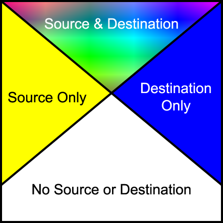
Depending on the compositing operation the resultant pixel includes input from one or more of the regions in the above diagram. For the regions where only source or destination are present, a choice of including or not including the input is available. For the region where both are present, various options are available for the combination of input data.
Depending on various attributes of a container element , the elements within the container element, are either combined to generate a single element, or the elements within the container element, are rendered onto the canvas independently. A container element, may be just a change in graphics context, or just a collection of elements, and as such the elements within the container element are rendered independently onto the canvas. Alternatively, a container element may have an opacity set to less than 100%, or an input filter applied to it, in which case the elements within the container element are first composited into a buffer, then treated as a single element to which the opacity, or an input filter is applied before the result is placed onto the canvas.
Implementation Note: Implementations may choose to implement groups using various techniques. An implementation has the option of creating buffers, and rendering as it sees fit to produce the results as described in this chapter.
Combinations of groups where background-enable is set to 'accumulate' combined with group opacity less than 1 and a comp-op other than 'src_over' requires application of a background removal technique. This needs to be incorporated into this description, either here, or as an appendix.
For groups containing compositing operators, the operation used to composite the group onto the canvas is the comp-op property of the container element itself. Other container element properties such as opacity specify operations to be performed to the group between the steps of combining the children, and compositing the group onto the background. The enable-background and knock-out properties specify the state the group buffer is initialized to prior to use, any modification to the compositing of the group's children, and in some cases a post rendering step to be performed after rendering the children and prior to any other post rendering steps.
Implementation Note: While container elements are defined as requiring an buffer to be generated, it is often the case that a user agent using various optimizations can choose not to generate this buffer. For example, a group containing a single object could be directly rendered onto the background rather than into an buffer first.
10.1.3 The clip-to-self property
-
clip-to-self
-
| Value: |
true | false | inherit
|
| Initial: |
false
|
| Applies to: |
container elements and graphics elements
|
| Inherited: |
no
|
| Percentages: |
N/A
|
| Media: |
visual
|
| Animatable: |
yes
|
The clip-to-self property determines if the object effects pixels not covered by the object. Some compositing operations effect pixels where the source graphic is completely transparent. Regions where the source graphic does not cover, one of two operations can be performed. Setting clip-to-self to true means that compositing an object only effects the pixels covered by the object. Setting clip-to-self to false means that compositing an object effects all pixels on the canvas by compositing completely transparent source onto the destination for areas not covered by the object.
The clip-to-self property provides compatibility with Java2D and PDF 1.4 transparency.
Implementation of this property will most likely require a so-called 'shape' channel in addition to an alpha channel. This may have issues regarding high-quality renderers which perform antialiasing. The group is considering issues related to the use of the shape channel for both antialiasing and container groups.
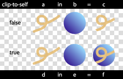
View this image as SVG (SVG-enabled browsers only)
10.1.4 The enable-background property
-
enable-background
-
| Value: |
accumulate | new [ x y width height ] | inherit
|
| Initial: |
accumulate
|
| Applies to: |
container elements
|
| Inherited: |
no
|
| Percentages: |
N/A
|
| Media: |
visual
|
| Animatable: |
no
|
For a simple group, enable-background is set to accumulate. For such groups, sub-objects are rendered directly onto the canvas.
For a complex group with enable-background set to new , the container element's buffer is initially cleared to transparent. This buffer is treated as the canvas for the complex group's children. When the complete contents of the container element are rendered onto the buffer, the buffer is composited onto the canvas, using the container element's specified compositing operation.
For a complex group with enable-background set to accumulate , the corresponding area of the canvas is copied into the container element's buffer. A second buffer which has only an opacity channel is also created. This buffer, the group opacity buffer, is initially transparent. The group buffer is treated as the canvas for the children of the complex group as usual. Additionally, as objects are placed into the buffer, the opacity part of the operation is repeated into the group opacity buffer. Before the group buffer is composited onto the canvas, the background color, masked by the group opacity buffer, is subtracted from the group buffer. Other post rendering steps such as the opacity are performed after this step, and before compositing the result onto the canvas.
The following equation is the method used to remove the color from the background contributing to the values in the buffer.
      BGc - The background color value.
      BGa - The background alpha value.
      Dc  - The buffer color value prior to background color removal.
      Da  - The buffer alpha value prior to background color removal.
      Da2 - The buffer secondary alpha value.
      Dc' - The buffer color value post background color removal.
      Da' - The buffer alpha value post background color removal.

      Dc' = Dc - BGc/BGa . (Da - Da2)
      Da' = Da2
Elements containing a comp-op property value of clear, src, dst, dst_over, src_in, dst_in, src_out, dst_out, src_atop, dst_atop, xor are only valid where the object's parent complex group has the enable-background property set to new. It is valid for such objects to be contained within nested simple groups, as long as the nearest ancestor that is a complex group has the enable-background property set to new. For elements without a parent complex group, or elements within a complex group where the enable-background property set to accumulate , these operations are technically an error. A user agent should ignore the operation specified and render the element using the src_over compositing operation.
Filters have access to the nearest ancestor complex group's buffer through the BackgroundImage and BackgroundAlpha images. The buffer created for the ancestor complex group element of the element referencing the filter, is passed to the filter. Where no ancestors of the element referencing the filter contain an enable-background property value of new, transparent black is passed as input to the filter.
The optional x, y, width, height parameters on the new value indicate the subregion of the container element's user space where input filters have access to the background image. These parameters enable the SVG user agent potentially to allocate smaller temporary image buffers than the effective bounds of the container element. Thus, the values x, y, width, height act as a clipping rectangle on the background image canvas. Negative values for width or height are an error. If more than zero but less than four of the values x, y, width and height are specified or if zero values are specified for width or height, BackgroundImage and BackgroundAlpha are processed as if enable-background property was set to accumulate .
Where a filter references an area of the background image outside the area specified by x, y, width, height, transparent is passed to the filter.
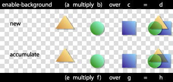
View this image as SVG (SVG-enabled browsers only)
10.1.5 The knock-out property
-
knock-out
-
| Value: |
true | false | inherit
|
| Initial: |
false
|
| Applies to: |
container elements
|
| Inherited: |
no
|
| Percentages: |
N/A
|
| Media: |
visual
|
| Animatable: |
no
|
For a complex group where the knock-out property is set, the buffer is created as usual. The initial contents of the buffer created, and whether a secondary opacity channel is created depends on the value of the enable-background property. For each object within the container element, the object color and opacity replaces that of other objects within the container element, rather than overlaying it as for normal compositing. In effect, the destination input to the compositing operations for the complex group's children is the original contents of the buffer, rather than the current buffer for the complex group.
For knock-out=false :
      Dc' = f(Sc, Sa, Dc, Da)
      Da' = f(Sa, Da)
For knock-out=true, enable-background=new :
      Dc' = f(Sc, Sa, 0, 0)
      Da' = f(Sa, 0)
For 'knock-out' =true ,'enable-background' =accumulate :
      Dc' = f(Sc, Sa, BGc, BGa)
      Da' = f(Sa, 0)
Note that an element in a knockout group that does not have the clip-to-self property set, in effect clears all prior elements in the group.
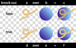
View this image as SVG (SVG-enabled browsers only)
10.1.6 The comp-op property
-
comp-op
-
| Value: |
clear | src | dst | src_over | dst_over | src_in | dst_in | src_out | dst_out | src_atop | dst_atop | xor | plus | multiply | screen | overlay | darken | lighten | color_dodge | color_burn | hard_light | soft_light | difference | exclusion | inherit
|
| Initial: |
src_over
|
| Applies to: |
container elements and graphics elements
|
| Inherited: |
no
|
| Percentages: |
N/A
|
| Media: |
visual
|
| Animatable: |
yes
|
The comp-op property determines the compositing operation used when placing elements onto the canvas. The canvas contains color components and an optional alpha component. When placing new elements onto the canvas, the resulting pixel values on the canvas are calculated using the equations listed in the sections below.
The diagram below shows the sub-pixel regions output by each of the compositing operations.
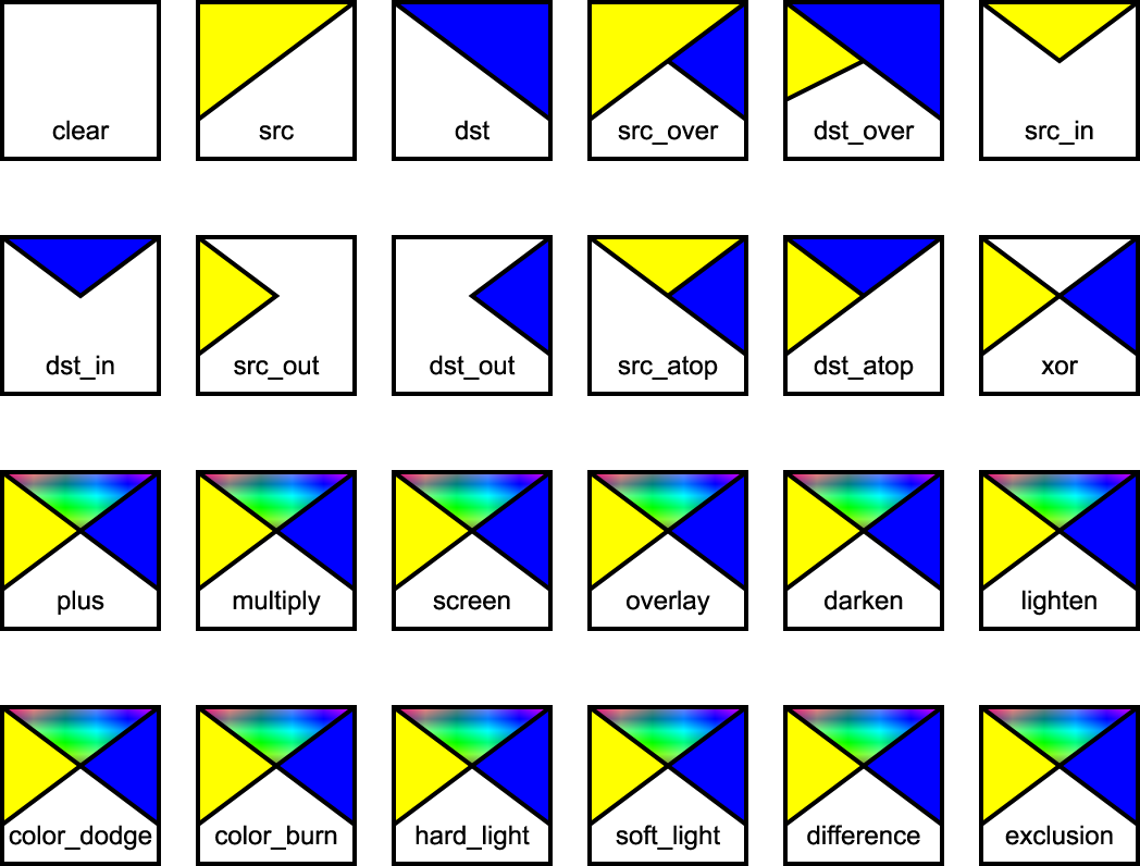
For many of the operators below, the destination is modified in regions of the image where the source is completely transparent. Pixels that the source does not touch are considered transparent, and as such may be modified, depending on the compositing operation. As discussed in the previous section, the bounds of the parent container element can be optimized to save in memory usage and hence, pixel writing requirements. Once the bounds of the parent container element have been determined, each element can only affect the pixels within those bounds.
The following operators change pixels where the source is transparent: clear src src_in dst_in src_out dst_atop
Implementation Note: The user agent may be required to create a backing store in which to generate a container element. The size of the backing store for a container element using the default compositing operator src_over is simply the union of the bounds of the sub-elements of the container element. When other compositing operators are used, the bounds of the container element are determined using the compositing operator diagram above. Starting with an empty bounds, the bounds of each successive object within the container element either replaces, is unioned with the result, or intersected depending on the compositing operator. For most compositing operators, the bounds are unioned with the result. For clear, the current result is set to empty. For src, src_out and dst_atop, the bounds are set to the source bounds. For dst, dst_out and src_atop, the bounds are left unchanged. For src_in and dst_in the bounds are intersected with the result.
All color components listed below refer to color component information pre-multiplied by the corresponding alpha value. The following identifiers have the attached meaning in the equations below:
      Sc  - The source element color value.
      Sa  - The source element alpha value.
      Dc  - The canvas color value prior to compositing.
      Da  - The canvas alpha value prior to compositing.
      Dc' - The canvas color value post compositing.
      Da' - The canvas alpha value post compositing.
-
clear
-
Both the color and the alpha of the destination are cleared. Neither
the source nor the destination are used as input.
  Dc' = 0
  Da' = 0
-
src
-
The source is copied to the destination. The destination is not used
as input.
  Dc' = Sc.Da + Sc.(1 - Da)
      = Sc
  Da' = Sa.Da + Sa.(1 - Da)
      = Sa
-
dst
-
The destination is left untouched.
  Dc' = Dc.Sa + Dc.(1 - Sa)
      = Dc
  Da' = Da.Sa + Da.(1 - Sa)
      = Da
-
src_over
-
The source is composited over the destination.
  Dc' = Sc.Da + Sc.(1 - Da) + Dc.(1 - Sa)
      = Sc + Dc.(1 - Sa)
  Da' = Sa.Da + Sa.(1 - Da) + Da.(1 - Sa)
      = Sa + Da - Sa.Da
The following diagram shows src_over compositing:
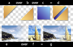
View this image as SVG (SVG-enabled browsers only)
-
dst_over
-
The destination is composited over the source and the
result replaces the destination.
  Dc' = Dc.Sa + Sc.(1 - Da) + Dc.(1 - Sa)
      = Dc + Sc.(1 - Da)
  Da' = Da.Sa + Sa.(1 - Da) + Da.(1 - Sa)
      = Sa + Da - Sa.Da
-
src_in
-
The part of the source lying inside of the destination
replaces the destination.
  Dc' = Sc.Da
  Da' = Sa.Da
The following diagram shows src_in compositing:
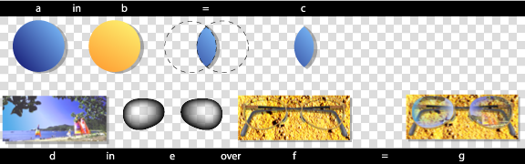
View this image as SVG (SVG-enabled browsers only)
-
dst_in
-
The part of the destination lying inside of the source
replaces the destination.
  Dc' = Dc.Sa
  Da' = Sa.Da
-
src_out
-
The part of the source lying outside of the destination
replaces the destination.
  Dc' = Sc.(1 - Da)
  Da' = Sa.(1 - Da)
The following diagram shows src_out compositing:
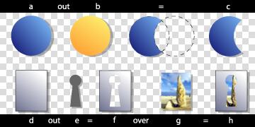
View this image as SVG (SVG-enabled browsers only)
-
dst_out
-
The part of the destination lying outside of the source replaces the destination.
 Dc' = Dc.(1 - Sa)
 Da' = Da.(1 - Sa)
-
src_atop
-
The part of the source lying inside of the destination is
composited onto the destination.
  Dc' = Sc.Da + Dc(1 - Sa)
  Da' = Sa.Da + Da(1 - Sa)
      = Da
The following diagram shows src_atop compositing:
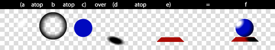
View this image as SVG (SVG-enabled browsers only)
-
dst_atop
-
The part of the destination lying inside of the source is composited over the source and replaces the destination.
  Dc' = Dc.Sa + Sc.(1 - Da)
  Da' = Da.Sa + Sa.(1 - Da)
      = Sa
-
xor
-
The part of the source that lies outside of the destination is
combined with the part of the destination that lies outside of the
source.
  Dc' = Sc.(1 - Da) + Dc.(1 - Sa)
  Da' = Sa.(1 - Da) + Da.(1 - Sa)
      = Sa + Da - 2.Sa.Da
The following compositing operators add blending of source and destination colors beyond the base 12 Porter-Duff operations. The behavior of these operators necessitates clamping of the output values after compositing.
-
plus
-
The source is added to the destination and replaces the destination. This operator is useful for animating a dissolve between two images.
  Dc' = Sc.Da + Dc.Sa + Sc.(1 - Da) + Dc.(1 - Sa)
      = Sc + Dc
  Da' = Sa.Da + Da.Sa + Sa.(1 - Da) + Da.(1 - Sa)
      = Sa + Da
-
multiply
-
The source is multiplied by the destination and replaces the destination. The resultant color is always at least as dark as either of the two constituent colors. Multiplying any color with black produces black. Multiplying any color with white leaves the original color unchanged.
  Dc' = Sc.Dc + Sc.(1 - Da) + Dc.(1 - Sa)
  Da' = Sa.Da + Sa.(1 - Da) + Da.(1 - Sa)
      = Sa + Da - Sa.Da
The following diagram shows multiply compositing:
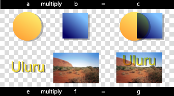
View this image as SVG (SVG-enabled browsers only)
-
screen
-
The source and destination are complemented and then multiplied and then replace the destination. The resultant color is always at least as light as either of the two constituent colors. Screening any color with white produces white. Screening any color with black leaves the original color unchanged.
  Dc' = (Sa.Da - (Da - Dc).(Sa - Sc)) + Sc.(1 - Da) + Dc.(1 - Sa)
      = (Sc.Da + Dc.Sa - Sc.Dc) + Sc.(1 - Da) + Dc.(1 - Sa)
      = Sc + Dc - Sc.Dc
  Da' = Sa + Da - Sa.Da
The following diagram shows screen compositing:

View this image as SVG (SVG-enabled browsers only)
-
overlay
-
Multiplies or screens the colors, dependent on the destination color. Source colors overlay the destination whilst preserving its highlights and shadows. The destination color is not replaced, but is mixed with the source color to reflect the lightness or darkness of the destination.
  if 2.Dc < Da
    Dc' = 2.Sc.Dc + Sc.(1 - Da) + Dc.(1 - Sa)
  otherwise
    Dc' = Sa.Da - 2.(Da - Dc).(Sa - Sc) + Sc.(1 - Da) + Dc.(1 - Sa)

  Da' = Sa + Da - Sa.Da
These equations are approximations which are under review. Final equations may differ from those presented here.
The following diagram shows overlay compositing:
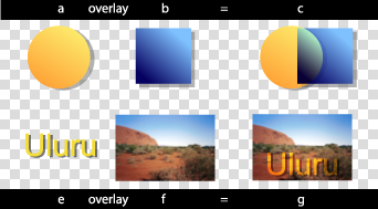
View this image as SVG (SVG-enabled browsers only)
-
darken
-
Selects the darker of the destination and source colors. The destination is replaced with the source when the source is darker, otherwise it is left unchanged.
  Dc' = min(Sc.Da, Dc.Sa) + Sc.(1 - Da) + Dc.(1 - Sa)
  Da' = Sa + Da - Sa.Da

  or

  if Sc.Da < Dc.Sa
    src_over()
  otherwise
    dst_over()
The following diagram shows darken compositing:
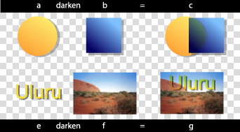
View this image as SVG (SVG-enabled browsers only)
-
lighten
-
Selects the lighter of the destination and source colors. The destination is replaced with the source when the source is lighter, otherwise it is left unchanged.
  Dc' = max(Sc.Da, Dc.Sa) + Sc.(1 - Da) + Dc.(1 - Sa)
  Da' = Sa + Da - Sa.Da

  or

  if Sc.Da > Dc.Sa
    src_over()
  otherwise
    dst_over()
The following diagram shows lighten compositing:
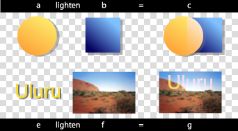
View this image as SVG (SVG-enabled browsers only)
-
color_dodge
-
Brightens the destination color to reflect the source color. Painting with black produces no change.
  if Sc.Da + Dc.Sa >= Sa.Da
    Dc' = Sa.Da + Sc.(1 - Da) + Dc.(1 - Sa)
  otherwise
    Dc' = Dc.Sa/(1-Sc/Sa) + Sc.(1 - Da) + Dc.(1 - Sa)

  Da' = Sa + Da - Sa.Da
These equations are approximations which are under review. Final equations may differ from those presented here.
The following diagram shows color_dodge compositing:
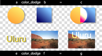
View this image as SVG (SVG-enabled browsers only)
-
color_burn
-
Darkens the destination color to reflect the source color. Painting with white produces no change.
  if Sc.Da + Dc.Sa <= Sa.Da
    Dc' = Sc.(1 - Da) + Dc.(1 - Sa)
  otherwise
    Dc' = Sa.(Sc.Da + Dc.Sa - Sa.Da)/Sc + Sc.(1 - Da) + Dc.(1 - Sa)

  Da' = Sa + Da - Sa.Da
These equations are approximations which are under review. Final equations may differ from those presented here.
The following diagram shows color_burn compositing:
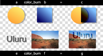
View this image as SVG (SVG-enabled browsers only)
-
hard_light
-
Multiplies or screens the colors, dependent on the source color value. If the source color is lighter than 0.5, the destination is lightened as if it were screened. If the source color is darker than 0.5, the destination is darkened, as if it were multiplied. The degree of lightening or darkening is proportional to the difference between the source color and 0.5. If it is equal to 0.5 the destination is unchanged. Painting with pure black or white produces black or white.
  if 2.Sc < Sa
     Dc' = 2.Sc.Dc + Sc.(1 - Da) + Dc.(1 - Sa)
  otherwise
     Dc' = Sa.Da - 2.(Da - Dc).(Sa - Sc) + Sc.(1 - Da) + Dc.(1 - Sa)

  Da' = Sa + Da - Sa.Da
These equations are approximations which are under review. Final equations may differ from those presented here.
The following diagram shows hard_light compositing:
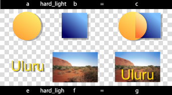
View this image as SVG (SVG-enabled browsers only)
-
soft_light
-
Darkens or lightens the colors, dependent on the source color value. If the source color is lighter than 0.5, the destination is lightened. If the source color is darker than 0.5, the destination is darkened, as if it were burned in. The degree of darkening or lightening is proportional to the difference between the source color and 0.5. If it is equal to 0.5, the destination is unchanged. Painting with pure black or white produces a distinctly darker or lighter area, but does not result in pure black or white.
  if 2.Sc < Sa
     Dc' = Dc.(Sa - (1 - Dc/Da).(2.Sc - Sa)) + Sc.(1 - Da) + Dc.(1 - Sa)
  otherwise if Dc.8 <= Da
     Dc' = Dc.(Sa - (1 - Dc/Da).(2.Sc - Sa).(3 - 8.Dc/Da)) + Sc.(1 - Da) + Dc.(1 - Sa)
  otherwise
     Dc' = (Dc.Sa + ((Dc/Da)^(0.5).Da - Dc).(2.Sc - Sa)) + Sc.(1 - Da) + Dc.(1 - Sa)

  Da' = Sa + Da - Sa.Da
These equations are approximations which are under review. Final equations may differ from those presented here.
The following diagram shows soft_light compositing:
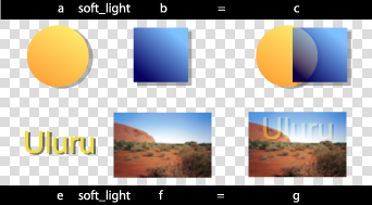
View this image as SVG (SVG-enabled browsers only)
-
difference
-
Subtracts the darker of the two constituent colors from the lighter. Painting with white inverts the destination color. Painting with black produces no change.
  Dc' = abs(Dc.Sa - Sc.Da) + Sc.(1 - Da) + Dc.(1 - Sa)
      = Sc + Dc - 2.min(Sc.Da, Dc.Sa)
  Da' = Sa + Da - Sa.Da
The following diagram shows difference compositing:
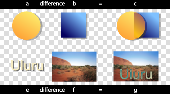
View this image as SVG (SVG-enabled browsers only)
-
exclusion
-
Produces an effect similar to that of 'difference', but appears as lower contrast. Painting with white inverts the destination color. Painting with black produces no change.
  Dc' = (Sc.Da + Dc.Sa - 2.Sc.Dc) + Sc.(1 - Da) + Dc.(1 - Sa)
  Da' = Sa + Da - Sa.Da
These equations are approximations which are under review. Final equations may differ from those presented here.
The following diagram shows exclusion compositing:
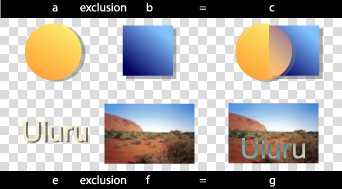
View this image as SVG (SVG-enabled browsers only)
10.1.7 Alternate Proposal for compositing
This is an alternate proposal for compositing syntax. It builds upon the Rendering Arbitrary XML feature described above. It is less complete than the proposal above which has been more thoroughly checked (mathematically).
The goal of this compositing proposal is to achieve the same functionality as the above proposal, but without changing the underlying rendering model. In summary:
-
No extra compositing logic is added to implementation. Rather it
uses the existing filter system and the rendering arbitrary XML
feature to map compositing operations into filters.
-
The filter logic may have to be updated to handle the clip-to-self
functionality.
-
It addresses the issue of complex groups requiring an extra channel
for shape opacity.
-
The memory allocation controls from filters are used, allowing
authors to limit the area to which compositing operations apply,
especially in the cases where offscreen buffers are necessary.
There will be two new elements added to the SVG language: composite and blend. Each has a predefined translation into a shadow tree. For example:
<composite op="over" x="0" y="0" width="100" height="100"
    filterUnits="userSpaceOnUse" filterRes="100 100">

  <!-- arbitrary SVG content -->

</composite>
The above example would be mapped into:
<g>
  <defs>
     <filter id="comp1" x="100" y="100" width="100" height="100"
        filterUnits="userSpaceOnUse" filterRes="100 100">
        <feComposite operator="over"/>
     </filter>
  </defs>

  <g filter="url(#comp1)">
     <!-- referenced content of 'composite' element -->
  </g>
</g>
In order to facilitate clip-to-self and the shape channel, the filter mechanism should add a shape attribute to all filter primitives which provides the same functionality as the Java2D clip-to-self feature and most common PDF shape channel algorithm. If the attribute is set then there will be a single channel mask which restricts the area upon which the filter is operating.
For example:
<blend op="multiply" x="0" y="0" width="100" height="100"
    filterUnits="userSpaceOnUse" filterRes="100 100"
    shape="sourceShape">

  <!-- arbitrary SVG content -->

</blend>
The above example gets translated into:
<g>
  <defs>
     <filter id="comp2" x="100" y="100" width="100" height="100"
        filterUnits="userSpaceOnUse" filterRes="100 100">
        <feBlend mode="multiply" shape="sourceShape"/>
     </filter>
  </defs>

  <g filter="url(#comp2)">
     <!-- referenced content of 'composite' element -->
  </g>
</g>
Implementations would be able to optimize their code to directly implement composite and blend without resorting to filters or shadow trees. The shadow tree logic represents the defined correct behavior, not the required implementation approach.
10.2 Drawing Order
Previous drafts of SVG 1.2 mentioned the possibility of a z-index property to allow separation of document order from drawing order. After long consultations with implementors and content developers, the SVG Working Group has decided not to add the feature. Instead, SVG 1.2 adds a technique to enable multiple layers or canvases that are displayed above the regular SVG canvas. This new feature is described below.
It is possible to simulate z-index the moment either using SMIL animation and multiple use elements, or through scripting (moving an element toward the end of the document). However, both can place restrictions on document structure, and have limitations due to property inheritance.
In the next draft there will be a feature which enables the author to place graphics above the canvas.
There are many situations in which the user wishes to have greater control over the coordinate system used by an object. An example is a legend on a map, which should retain the same position and size regardless of the transformation applied to user space by the user agent, such as zoom and pan.
SVG 1.2 extends the syntax of the transform attribute to provide a set of constrained transforms.
The new type of transform definition is:
-
ref(target [x y]), which specifies a transformation
matrix that converts the object's coordinate system into
a referenced coordinate system. If x and y are not
provided, they are assumed to be zero.
The value of 'target' can either be a local id URI reference or the special keyword 'host'.
The new transformation definition behaves in the same manner as the existing definitions in that it can be expressed as a transformation matrix which forms part of the coordinate system evaluation. However, the transformation matrix corresponding to the 'ref' definition depends on the current state of the document, rather than simply the definition parameters.
A value of 'ref(target)' evaluates to the matrix that is the inverse of the current user space matrix multiplied by the user space matrix of the referenced target element. The resulting effect is that the coordinate space of the transformed element becomes the coordinate space of the referenced element.
A value of 'ref(target, x, y)' is equivalent to 'ref(target)' with an additional translation so that the point (0,0) in the resulting coordinate space is mapped to the point (x,y) in the initial coordinate space.
When the target is the 'host' keyword, then the referenced element is found by starting from the current element and moving up in the tree until an element with a transform-host property set to 'true' is found. If no such element is found then:
-
if the tree is referenced by an element from the SVG language, then
the search continues from the referencing element
-
otherwise, there if no referenced element. Instead, the topmost
element's initial viewport coordinate space, before zoom, pan or
viewBox transformations are applied, is used as the host coordinate
space.
The following example shows text which does not move or scale on pan or zoom, regardless of the transform at element "a":
<svg>
   <g id="a" transform="...">
       <text transform="ref(host)">Text</text>
   </g>
</svg>
The next example shows text which moves along with the point (20,30) in the user space, but does not scale:
<svg>
   <g id="a" transform="...">
       <text transform="ref(host,20,30)">Text</text>
   </g>
</svg>
The transform-host property defines an element to act as the default transformation host for its children or referenced content.
-
transform-host
-
| Value: |
true | false
|
| Initial: |
false
|
| Applies to: |
container elements, use, image, feImage
|
| Inherited: |
no
|
| Percentages: |
N/A
|
| Media: |
visual
|
| Animatable: |
yes
|
The following example shows an image that can embed any of the previous constrained transform examples ensuring they all transform correctly in relation to the image element.
<svg>
    <g id="computer" transform="...">
       <image id="computer_screen" xlink:href="..." transform-host="true"/>
   </g>
</svg>
11 Painting Enhancements
11.1 The solidColor Element
The solidColor element is a paint server that provides a single color with opacity. It can be referenced like the other paint servers (gradients and patterns).
<xs:element name="solidColor">
  <xs:complexType>
    <xs:attributeGroup ref="PresentationAttrs"/>
    <xs:attributeGroup ref="StyleAttrs"/>
  </xs:complexType>
</xs:element>
The solid-color property indicates what color to use for this solidColor element. The keyword currentColor and ICC colors can be specified in the same manner as within a <paint> specification for the fill and stroke properties.
-
solid-color
-
| Value: |
currentColor | <color> [icc-color( <name> [, <icccolorvalue>]* ) ] | inherit
|
| Initial: |
black
|
| Applies to: |
solidColor elements
|
| Inherited: |
no
|
| Percentages: |
N/A
|
| Media: |
visual
|
| Animatable: |
yes
|
The solid-opacity property defines the opacity of a given solid color.
-
solid-opacity
-
| Value: |
<alphavalue> | inherit
|
| Initial: |
1
|
| Applies to: |
solidColor elements
|
| Inherited: |
no
|
| Percentages: |
N/A
|
| Media: |
visual
|
| Animatable: |
yes
|
11.2 Background Fill Property
SVG 1.2 will enable the author to specify a paint server which will be used to fill the background of any element that creates a viewport, such as the root svg element. In SVG 1.2, the referenced paint server is restricted to being a solid color. Future versions of SVG may allow arbitrary paint servers, such as gradients and patterns.
The background-fill property defines the paint used to fill the viewport created by a particular element.
-
background-fill
-
| Value: |
<paint>
|
| Initial: |
none
|
| Applies to: |
viewport-creating elements
|
| Inherited: |
no
|
| Percentages: |
N/A
|
| Media: |
visual
|
| Animatable: |
yes
|
It is an error to reference a fill that is not a solid color operation. Below is an example of background-fill.
<svg xmlns="http://www.w3.org/2000/svg" version="1.2"
     background-fill="red">

  <!-- Everything here has a red background -->

  <!-- This rectangle is not filled, so the red background
        will show through -->
  <rect x="20" y="20" width="100" height="100"
        fill="none" stroke="black"/>

  <svg x="40" y="100" width="200" height="200"
       background-fill="green">

    <!-- Everything here has a green background -->

  </svg>

</svg>
11.3 Inheritance into the shadow tree
The shadowInherit property applies to elements that establish shadow trees and controls property inheritance in those shadow trees. In SVG 1.0 and 1.1, this behavior was fixed depending on the element name. This property regularizes control over the inheritance method and gives more flexibility to content creators.
-
shadowInherit
-
| Value: |
onDefine | onUse | none | inherit
|
| Initial: |
onDefine
|
| Applies to: |
all elements that establish shadow trees
|
| Inherited: |
no
|
| Percentages: |
N/A
|
| Media: |
visual
|
| Animatable: |
no
|
-
onDefine
-
Properties inherit into the shadow tree at their point of definition,
in other words from the element that defines the shadow tree.
In SVG 1.0 and 1.1, for example, marker elements behave like this. It is easy to make red markers that are used on multiple paths, and difficult to make markers that are the color of the path on which they are used. Similarly gradient elements behave like this; it is difficult to make a gradient one of whose stops is the currentColor for example.
-
onUse
-
Properties inherit into the shadow tree at their point of use, in
other words from the element that generates the shadow tree.
In SVG 1.0 and 1.1, for example, symbols behave like this. It is easy to make symbols that are used in multiple places, and inherit from the use element that references them.
-
none
-
There is no inheritance into the shadow tree. All properties on the
root element of the shadow tree are set to their initial values, as if
the shadow tree were in a separate document. This allows SVG content
to be created and then re-used without risk of styling changes from
the surrounding context.
-
inherit
-
(This is a useless value but we need to define what happens). If the
parent element is an element that establishes shadow trees then the
value is that of the shadowInherit property on the parent element.
Otherwise, it is the same as onDefine.
The User Agent default stylesheet for SVG 1.2 user agents, to give SVG 1.0/1.1 compatible styling, includes the following rules:
  symbol { shadowInherit: onUse; }
  image, feImage { shadowInherit: none; }
11.4 Using device colors
Certain print applications can improve printing quality by specifying colors by name or in an alternative color format. This often is referred to the use of 'spot' colors, device colors or inks, and usually means that a particular ink will be used for the color when it is printed. Furthermore, there are applications in the printing press industry where presses can be set up with different inks for different jobs. This means that the content creator will need to create content tailored to the particular press setup in order to obtain the best results.
The deviceColor element can be used to indicate an alternative color for a particular paint. This element will be mostly used in closed workflows, since the names of the inks and the parameters (percentages of each ink's color components) rarely have meaning outside the domain of the target device.
<xs:element name="deviceColor">
  <xs:complexType>
    <xs:attribute ref="href" use="required"
        namespace="http://www.w3.org/1999/xlink"/>
    <xs:attribute ref="name" use="required" type="string"/>
    <xs:anyAttribute namespace="##any" processContents="skip"/>
  </xs:complexType>
</xs:element>
-
xlink:href
-
A URI used to identify the device-specific information included in this element. If the User Agent does not recognize the URI (ie. is not able to recognize the particular device parameters) then the element should be ignored and should not be part of the rendering process.
Animatable: no
-
name
-
The name of this device-specific color information. The name attribute is used within the device-color specification within <paint> to reference this deviceColor element.
Animatable: no
The deviceColor element uses attributes from external namespaces to define the device specific properties that are to be used when the deviceColor is referenced from a <paint>.
The following example illustrates the use of deviceColor. There are two things to note:
-
The deviceColor element describes device specific setup information.
-
The device-color keyword is used as an alternative <paint> specification,
achieving the desired <paint> when the output is the named device (or when
the User Agent is able to understand the device specific information).
<svg xmlns="http://www.w3.org/2000/svg" version="1.2"
     xmlns:xlink="http://www.w3.org/1999/xlink"
     xmlns:ecpi="http://www.example.com/press/inks">

  <defs>
     <!-- describe a particular output device -->
     <deviceColor name="device-inks"
                  xlink:href="http://www.example.com/pressInks"
             ecpi:value="Cyan, Magenta, Yellow, Black, Silver, Gray, Green"/>
  </defs>

  <text x="100" y="150" font-family="Verdana" font-size="35"
        fill="rgb(22,33,44) device-color(device-inks, 11,55,66,77,0,0,88)" >

     Hello, out there

  </text>

</svg>
In the example above, a supplemental attribute, value, from a private namespace has been added. This example value attribute provides the definitions of colors or inks to be interpreted in the context of the URI specified. It is in a private namespace so that content and context authors can use any understood format to convey the necessary information. When the particular deviceColor element is referenced later by a device-color keyword specification, it is generally expected that the number of parameters following the name reference (1st parameter) in the function-like representation for the value of device-color alternate in a fill or stroke attribute (for example) will have an understood one-to-one correspondence with the information specified for the value attribute in the the deviceColor element. The interpretation of the parameters is implied specifically by the context set by the URI.
11.4.1 The device-color keyword
The device-color keyword for specifying device specific <paint> colors is to be used only by those agents that understand the full meaning of the context set by the URI in the referred to DeviceColor element. The keyword can only be used with a corresponding color definition, such as a color keyword or RGB definition. The color definition, with ICC Color specification when present, is used if the agent does not understand the rendering context implied by the referenced device-color URI. The priority of the use of color specifications are as follows: device-color if understood, color-profile if present and understood and finally the sRGB specification.
The first parameter in the function like representation device-color must be the name for a defined deviceColor element, in a manner similar to color-profile. The remainder of the parameters are interpreted entirely in light of the information provided in the deviceColor element. There is a correspondence between the parameters after the name in the functional representation for device-color and the external attributes on the referenced deviceColor. In the example above, the interpretation of the values meaning (ink volume to use, percent of total ink volume, or whatever) is strictly in the context of the specification or convention implied by the URI in the referenced deviceColor element.
Addition of this keyword will modify the definition of the <paint> type. For this draft, we just include the definition of the keyword. Future drafts will specify the new <paint> type in full.
11.4.2 DOM Interface
Interface SVGDeviceColorElement
provides access to the deviceColor element.
IDL Definition-
interface SVGDeviceColorElement : SVGURIReference {
  readonly attribute DOMString name; // raises DOMException on setting
};
- Attributes
-
-
readonly
DOMString
name
-
Corresponds to the attribute 'name' on the given element
11.5 Controlling the rendering color space
SVG 1.2 adds a new property to give increased control over the color space used for rendering.
The SVG Working Group are considering removing this new feature from SVG 1.2 due to lack of interest. If it is removed it may be considered for future versions of the SVG language. If you have a need for this feature in the short term, please give feedback to the SVG Working Group. The same applies if you have implemented the feature.
11.5.1 The rendering-color-space property
The rendering-color-space property defines the color space that an element's rendering operations will take place in. Conceptually this involves the creation of an offscreen buffer with color space is defined by the ICC profile referenced by the property. All fill/stroke/gradient/pattern specifications must be converted to this color space before elements are rendered. Images and the results of filtering must be color converted, when required, to the specified color space before being composited. After the object/group is rendered the offscreen image must be converted to the color space defined by the rendering-color-space property on the object/group's parent before being composited into the parent's offscreen buffer.
The ICC profile referenced must provide forward and reverse conversion, as the implementation will need to convert to and from the specified color space; most ICC profiles provide both conversions. To limit the burden on implementors only three channel ICC profiles are required to be supported. In cases where the specified ICC profile can not be used (such as not being available, or because it has more than three channels of output) the implementation must use the rendering-color-space specification from the first ancestor that has a usable profile associated (i.e. it is as if a value was not provided for this property for this element).
Note that standard SVG compositing rules are used. As a consequence highly non-linear color spaces (such as HSV) or non-orthogonal color spaces (such as CMYK) may give unintuitive results when blending colors.
-
rendering-color-space
-
| Value: |
auto | sRGB | linearRGB | <name> | <uri> |inherit
|
| Initial: |
auto
|
| Applies to: |
container elements and graphical elements
|
| Inherited: |
yes
|
| Percentages: |
N/A
|
| Media: |
visual
|
| Animatable: |
yes
|
-
auto
-
The user agent must defer to the 'color-interpolation' property.
-
sRGB
-
Specifies that the sRGB color space is to be used for rendering.
-
linearRGB
-
Specifies that the linear sRGB color space is to be used for rendering.
-
<name>
-
A name corresponding to a defined color profile that is in the user
agent's color profile description database. The user agent searches
the color profile description database for a color profile
description entry whose name descriptor matches <name> and uses the
last matching entry that is found. If no match is found then it is
as if 'sRGB' were specified.
-
<uri>
-
A URI reference to the source color profile to use for rendering.
The color-interpolation property on gradients and color-interpolation-filters property on filter primitives are also extended to support <name> and <uri> references. This enables gradients and filters where interpolation occurs in an alternate color space. When the gradient is rendered the colors must be converted to the rendering-color-space of the object the gradient is applied to (consistent with the current definition of color-interpolation).
The color-interpolation property on graphics elements will be deprecated. The current definition of color-interpolation states that when the property is set on an element it controls what color space is used when the child is composited with it's parent.
The problem with this definition is that it implicitly requires converting the content already rendered into the parents buffer to the color space specified by color-interpolation for compositing with the child. This made sense when the only supported color spaces were sRGB and linear sRGB, because presumably the compositing code would perform the conversion, composite and convert back all at once, thus preserving the fidelity of the parent buffer. However it would be extremely difficult and computationally expensive for implementations to do this for arbitrary ICC color spaces.
Given this definition, for the use of the color-interpolation property to be make sense, the property would generally have to be set on all the children of a grouping element, but not be set on the grouping element. This would allow an implementation to composite all the children in the desired color space, and only convert to the 'parent' color space at the end of the group. However having to set a property on all the children but not on the parent would be extremely fragile as well as error prone for generators of SVG content.
Thus the SVG working group has decided that rendering-color-space should replace color-interpolation for use on graphics elements, it allows a clearer expression of the authors intent, and makes costly mistakes (both in speed and quality) less likely.
The user agent will go into error if the value of rendering-color-space is anything but 'auto' when color-interpolation has a value of 'linearRGB'. If color-interpolation is removed a future version of the specification the 'auto' value for rendering-color-space will be defined to mean 'sRGB'.
Should this property apply (or not) to implementations with more than 3 channels?
11.6 Filter Region extensions
In SVG 1.1, a filter defines the area upon which it applies. This makes it difficult to develop a generic filter that can be applied to arbitrary graphics, since the filter must define a large enough area to cover any graphical object to which it is applied. An example of this is a generic "drop shadow" filter, which is commonly specified as a combination of a Gaussian blur feGuassianBlur) that is offset feOffset) and then composed feComposite) with the original source graphic. Since the shadow has to extend beyond the original graphic's boundaries, the filter must be defined to have a larger area than the original graphic. Overestimating this margin has a negative effect on performance, since the complex filter operation has to touch a larger amount of user space (ie. pixels).
In order to solve this problem, SVG 1.2 adds margins to the filter and filter primitive elements. These margins are added to the filter region, once any conversion of the filter region from object space into user space has been made.
In particular, the filterMarginsUnits, filterPrimitiveMarginsUnits, dx, dy, dw and dh are added to the filter element. The filterMarginsUnits specifies the coordinate space of the new margin attributes, which are used to increase or decrease the filter element's x, y, width and height attributes (once they have been calculated). The filterPrimitiveMarginsUnits specifies the units for the new margin attributes on the filter primitives, also named dx, dy, dw, dh. These margins attribute override those set on the parent filter element.
An example of the new attributes, which defines a generic dropShadow filter:
<filter id="dropShadow" x="0" y="0" width="1" height="1"
          filterMarginsUnits="userSpaceOnUse"
          dx="0" dy="0" dw="5" dh="5" >
      <feGaussianBlur stdDeviation="2" in="SourceAlpha" />
      <feOffset dx="2" />
      <feMerge>
           <feMergeNode />
           <feMergeNode in="SourceGraphic" />
      </feMerge>
</filter>
In the above example, the filter region by default covers the entire bounds of the object (which is not enough to show the shadow). Adding the new margins extends the width and height by 5 user units each, which is always enough to display the blur (which has a standard deviation of 2 user units) and offset (which is another 2 units).
11.7 Hinting SVG Fonts
When displaying text on low-resolution devices or at very small sizes on higher-resolution devices it is common for a User Agent to use what is called a 'hinted' version of a scalable font. Many popular font formats, such as TrueType and Postscript, allow hinting. Typically this is a set of instructions to the text layout system that, when followed, will produce optimum legibility. This could include instructions on placing parts of the glyph on pixel boundaries or instructions on keeping the width of adjacent glyph stems constant.
The font format included in SVG 1.1 does not allow hinting. This is seen as a shortcoming in situations where the available resolution is insufficient to display the glyphs well, and where legibility of the text is considered more important than preserving the typographic color of the font used. This has meant that authors are embedding fonts in other formats inside SVG documents.
SVG 1.2 plans to add hinting as an optional feature on SVG fonts in order to give authors the choice of a pure SVG solution. The main requirements are that the hinting technology be declarative, work on non axis aligned text (eg. rotated text) and available royalty-free to SVG implementations. The most likely solution is a variation of Postscript Type 1 hinting.
11.8 Prefetching resources
In SVG 1.1 it is not clear when an user agent should begin downloading references media, particularly when the media is not used in the initial document state (e.g. it is offscreen or hidden). SVG 1.2 does not require user agents to download referenced media that is not visual at the time the document is loaded. This means there may be a pause to download the file the first time a piece of media is displayed. More advanced user agents may wish to predict that particular media streams will be needed and therefore download them in anticipation.
SVG 1.2 also adds functionality (adapted from Section 4.4 of SMIL 2.0 — The PrefetchControl Module) to allow content developers to suggest fetching content from the server before it is needed to improve the rendering performance of the document.
11.8.1 The prefetch element
The prefetch element will give a suggestion or hint to a user agent that a media resource will be used in the future and the author would like part or all of the resource fetched ahead of time to make the document playback smoother. User-agents can ignore prefetch elements, though doing so may cause an interruption in the document playback when the resource is needed. It gives authoring tools or savvy authors the ability to schedule retrieval of resources when they think that there is available bandwidth or time to do it.
The prefetch element is a particular type of animation element. The full details of how prefetch fits into the animation model of SVG is not described in this draft. As SVG 1.2 adds more of the planned SMIL features, such as video, audio, par and seq, the behavior of the prefetch element will be described in full.
<xs:element name="prefetch">
  <xs:complexType>
    <xs:attribute ref="href" use="required"
        namespace="http://www.w3.org/1999/xlink"/>
    <xs:attributeGroup ref="StdAttrs"/>
    <xs:attribute ref="mediaSize"/>
    <xs:attribute ref="mediaTime"/>
    <xs:attribute ref="bandwidth"/>
  </xs:complexType>
</xs:element>
-
mediaSize = " <number> | <percentage>"
-
Defines how much of the resource to fetch as a function of the file
size of the resource. To fetch the entire resource without knowing
its size, specify 100%. The default is 100%.
-
mediaTime = " <clock> | <percentage>"
-
Defines how much of the resource to fetch as a function of the
duration of the resource. To fetch the entire resource without
knowing its duration, specify 100%. The default is 100%. For
discrete media (non-time based media like image/png)
using this attribute causes the entire resource to be fetched.
-
bandwidth = " <number> | <percentage>"
-
Defines how much network bandwidth the user agent should use when
doing the prefetch. To use all that is available, specify 100%. The
default is 100%.
Any attribute with a value of "0%" is ignored and treated as if the attribute wasn't specified.
If both mediaSize and mediaTime are specified, mediaSize is used and mediaTime is ignored.
Below is an example of the prefetch element:
<svg width="400" height="300" version="1.2"
     xmlns="http://www.w3.org/2000/svg"
     xmlns:xlink="http://www.w3.org/1999/xlink">
  <desc>
     Prefetch the large images before starting the animation
     if possible.
  </desc>

  <defs>
    <prefetch id="pf1" xlink:href="http://www.example.com/images/huge1.png"/>
    <prefetch id="pf2" xlink:href="http://www.example.com/images/huge2.png"/>
    <prefetch id="pf3" xlink:href="http://www.example.com/images/huge3.png"/>
  </defs>

  <image x="0" y="0" width="400" height="300"
     xlink:href="http://www.example.com/images/huge1.png"
     display="none">

     <set attributeName="display" to="inline" begin="10s"/>

     <animate attributeName="xlink:href" values="
            http://www.example.com/images/huge1.png;
            http://www.example.com/images/huge2.png;
            http://www.example.com/images/huge3.png"
         begin="15s" dur="30s"/>
  </image>

</svg>
11.9 Referencing external stylesheets
SVG 1.2 adds the xlink:href attribute to the style element, allowing the reference of external stylesheets. The attribute behaves in the same way as the corresponding attribute on the script element.
11.10 Increased switch availability
SVG 1.2 will allow the switch element to be a child of more elements — potentially all elements.
The full details of this feature will be available once the complete draft schema is created.
12 Alternate content based on display resolutions
An image may be placed at any location in userspace, and be subject to any set of affine transformations. In many cases, the resolution at which a raster image is rendered, whether to screen or another device, may not be a good match to the resolution of the image itself. For example, it is not efficient to load a 4000 by 4000 pixel image to be eventually rendered in a 10 pixel by 10 pixel region if an appropriate thumbnail was available at that size.
For this reason, SVG 1.2 will add enhancements to images which will allow multiple resources to be used for a single image. The choice of resource is governed by the output resolution.
The current proposal is to do this by extending the test attributes of the switch element. Below is an example:
<svg width="400" height="400">
      <g id="backgroundLayer">
         ...
      </g>
      <switch>
          <!-- Only show if 10 pixels (or more) make a -->
          <!-- user unit (very zoomed in)              -->
          <!-- The detailed area is divided into 16    -->
          <!-- tiles.                                  -->
          <g id="veryDetailed" min-unit-scale="10">
             <g id="tile_0_0" requiredView="0 0 100 100">
                 ...
             </g>
             <g id="tile_1_0" requiredView="100 0 100 100">
                 ...
             </g>
             <g id="tile_2_0" requiredView="200 0 100 100">
                 ...
             </g>
             ...
             <g id="tile_3_3" requiredView="300 300 100 100">
                 ...
             </g>
          </g>


          <!-- Only show for 1-10 pixels in a user unit -->
          <!-- (somewhat zoomed in)                     -->
          <!-- The detailed area is divided into 4      -->
          <!-- tiles.                                   -->
          <g id="somewhatDetailed"
             min-unit-scale="1" max-unit-scale="10">
             <g id="tile_0_0" requiredView="0 0 200 200">
                 ...
             </g>
             <g id="tile_1_0" requiredView="200 0 200 200">
                 ...
             </g>
             <g id="tile_0_1" requiredView="0 200 200 200">
                 ...
             </g>
             <g id="tile_1_1" requiredView="200 200 200 200">
                 ...
             </g>

          </g>
          <!-- Show for 1 pixel and down (zoom out)-->
          <g id="roughlyDetailed" max-unit-scale="1">
              ...
          </g>
     </switch>
 </svg>
The following sections should be read as updating the equivalent sections from Chapter 5 of the SVG 1.1 Recommendation.
12.1 Conditional processing
12.1.1 Conditional processing overview
SVG contains a 'switch' element along with attributes requiredFeatures, requiredExtensions, systemLanguage, min-unit-scale and max-unit-scale to provide an ability to specify alternate viewing depending on the capabilities of a given user agent, the user's language or the current transform between the user space and the device space
     <xs:attribute ref="requiredFeatures"/>
     <xs:attribute ref="requiredExtensions"/>
     <xs:attribute ref="systemLanguage"/>
     <xs:attribute ref="min-pixel-size"/>
     <xs:attribute ref="max-pixel-size"/>
     <xs:attribute ref="requiredView"/>
Attributes requiredFeatures, requiredExtensions, systemLanguage, requiredView, min-unit-scale and max-unit-scale act as tests and return either true or false results. The 'switch' renders the first of its children for which all of these attributes test true. If the given attribute is not specified, then a true value is assumed.
Similar to the 'display' property, conditional processing attributes only affect the direct rendering of elements and do not prevent elements from being successfully referenced by other elements (such as via a 'use').
In consequence:
-
requiredFeatures, requiredExtensions, systemLanguage requiredView,
min-unit-scale and max-unit-scale attributes affect 'a', 'altGlyph',
'foreignObject', 'textPath', 'tref', and 'tspan' elements.
-
requiredFeatures, requiredExtensions, systemLanguage requiredView,
min-unit-scale and max-unit-scale attributes will have no effect on
'mask', 'clipPath', and 'pattern' elements.
-
requiredFeatures, requiredExtensions, systemLanguage requiredView,
min-unit-scale and max-unit-scale attributes do not apply to the
'defs', and 'cursor' elements because they are not part of the
rendering tree.
-
requiredFeatures, requiredExtensions, systemLanguage requiredView,
min-unit-scale and max-unit-scale attributes affect 'animate',
'animateColor', 'animateMotion', 'animateTransform', and 'set'
elements. The SVG Working Group is discussing how to specify the
impact of conditional processing on animations.
The 'switch' element evaluates the requiredFeatures, requiredExtensions, systemLanguage requiredView min-unit-scale and max-unit-scale attributes on its direct child elements in order, and then processes and renders the first child for which these attributes evaluate to true. All others will be bypassed and therefore not rendered. If the child element is a container element such as a 'g', then the entire subtree is either processed/rendered or bypassed/not rendered. The test conditions must be evaluated whenever the corresponding context values change (e.g., the user language preferences) change and/or when the criteria change (e.g., the systemLanguage attribute) change.
Note that the values of properties 'display' and 'visibility' have no effect on 'switch' element processing. In particular, setting 'display' to none on a child of a 'switch' element has no effect on true/false testing associated with 'switch' element processing.
12.2 The requiredView attribute
The requiredView attribute specifies an area in the current user space. The requiredView attribute has the same syntax as the viewport attribute and defines an area in the same way the viewport attribute does but for a different purpose. If the area defined by requiredView intersects with the displayed area of its viewport, then the requiredView condition evaluates to true. Otherwise, it evaluates to false.
12.3 The min-pixel-width and max-pixel-width attributes
The min-unit-scale and max-unit-scale attributes refer to the scale factor in the transform between the element's user space and the viewport space. These attributes are allowed to provide one or two values. If two values are provided then the first refers to the scale factor in the horizontal direction and the second value refers to the scale factor in the vertical direction. If one value is provided it is used for both the horizontal and vertical scale factors.
When implementations evaluate these attributes they should pay attention to the possibility that the content is being rendered in a filter using the filterRes attribute when calculating the scale factor from the current coordinate system to the viewport coordinate system.
If the scale factor from the current user coordinate system to the viewport coordinate system is greater than min-unit-scale, then the test evaluates to true. If the scale factor from the current user coordinate sytsem to the viewport coordinate system is smaller than max-unit-scale, then the test evaluates to true. Otherwise, the tests evaluate to false.
The min-unit-scale and max-unit-scale attributes are often used in conjunction with the 'switch' element. If the min-unit-scale and/or max-unit-scale attributes are used in other situations, then they represents a simple switch on the given element whether to render the element or not.
13 Vector Effects
13.1 The vectorEffect element
The vectorEffect element defines a transformation of a primitive shape's outline that happens before it is drawn. The transformation is described as a series of vector effect primitive processing nodes, where input(s) and the output of every node can be considered to be SVG path data. Any primitive shape or path element can reference a vector effect through the vector-effect property. Alternatively, vector effects can be used as a drawing element; in such case its input is considered to be empty (and the vePath element must be used to get input data).
The following is an extract of the schema that defines the vectorEffect element:
<xs:element name="vectorEffect">
  <xs:complexType>
    <xs:sequence>
      <xs:element ref="vePath" minOccurs="0" maxOccurs="unbounded"/>
      <xs:element ref="veSetback" minOccurs="0" maxOccurs="unbounded"/>
      <xs:element ref="veStrokePath" minOccurs="0" maxOccurs="unbounded"/>
      <xs:element ref="veAffine" minOccurs="0" maxOccurs="unbounded"/>
      <xs:element ref="veJoin" minOccurs="0" maxOccurs="unbounded"/>
      <xs:element ref="veReverse" minOccurs="0" maxOccurs="unbounded"/>
      <xs:element ref="veUnion" minOccurs="0" maxOccurs="unbounded"/>
      <xs:element ref="veIntersect" minOccurs="0" maxOccurs="unbounded"/>
      <xs:element ref="veExclude" minOccurs="0" maxOccurs="unbounded"/>
      <xs:element ref="veFill" minOccurs="0" maxOccurs="unbounded"/>
      <xs:element ref="veStroke" minOccurs="0" maxOccurs="unbounded"/>
      <xs:element ref="veMarker" minOccurs="0" maxOccurs="unbounded"/>
      <xs:element ref="veMarkerPath" minOccurs="0" maxOccurs="unbounded"/>
    </xs:sequence>
    <xs:attribute ref="vectorEffectUnits"/>
    <xs:attribute ref="compositing"/>
  </xs:complexType>
</xs:element>
The vectorEffectUnits attribute allows "userSpaceOnUse" or "objectBoundingBox" as values. The default is "userSpaceOnUse". The output of the last vector effect node is considered to be the result of the complete vector effect. That path is used when shape's outline is normally used (inside clipPath, for text flows and text on a path, and when referenced by a vePath element).
The compositing attribute allows "normal" or "knockout" as values. The value "normal" means that results of the individual fill operations are composited with each other as usual. The value "knockout" means that fill operations that go later in the pipeline override current values rather than mix with them.
This proposal includes some vector effect primitives that are still under discussion. In many cases there will have to be a implementation cost versus usage benefit decision. Please provide feedback on what primitives you would find the most useful.
This is the default vectorEffect that corresponds to the default SVG painting behavior:
<vectorEffect>
  <veFill/>
  <veStroke/>
  <veMarker/>
</vectorEffect>
13.2 Common vector effect primitive attributes
The following attributes are available on all vector effect primitives.
-
result = name of output
-
The result attribute specifies the location, if necessary, of the output from the current vector effect primitive. It is analogous to the result attribute on filter effect primitives. If not specified, the value is empty, and the result is only passed to the following primitive. Animatable: no.
-
in = "SourcePath" | name of input
-
-
in2 = "SourcePath" | name of input
-
The in and in2 attributes define the input locations for the current vector effect primitive. The value of "SourcePath" means that the outline of the shape that references this effect is used. Any other value refer to the output of another node within this vectorEffect identified by the value of its result attribute. If this attribute is omitted, for the first primitive the value "SourcePath" value is used, and the output of the previous primitive is used for all other nodes. The path used for "SourcePath"is always pre-transformed to be in the correct coordinate space depending on the value of the vectorEffectUnits attribute value. Animatable: no
-
transform = <transform>
-
-
trandformPath = <transform>
-
The transform and transformPath attributes supply coordinate space transformations for some vector effect elements. The difference between them is that the transform attribute defines the coordinate space where a particular operation occurs, so that the input is transformed into to that coordinate space, the vector effect operation applied and then the inverse transform applied to the result. In contrast, transformPath is simply applied to the input of the particular operation. The default value is empty. Animatable: yes.
13.3 The veStrokePath element
<xs:element name="veStrokePath">
  <xs:complexType>
    <xs:attribute ref="result"/>
    <xs:attribute ref="in"/>
    <xs:attribute ref="transform"/>
    <xs:attribute ref="stroke-width"/>
    <xs:attribute ref="stroke-dasharray"/>
    <xs:attribute ref="stroke-dashoffset"/>
    <xs:attribute ref="stroke-linejoin"/>
    <xs:attribute ref="stroke-linecap"/>
    <xs:attribute ref="stroke-miterlimit"/>
  </xs:complexType>
</xs:element>
The veStrokePath element produces an outline of the input path's stroke calculated using the given stroke parameters. The default values for the parameters comes from the corresponding computed property values of the source element. Width attribute percentages are interpreted relative to the source element stroke-width property.
13.4 The veSetback element
<xs:element name="veSetback">
  <xs:complexType>
    <xs:attribute ref="result"/>
    <xs:attribute ref="in"/>
    <xs:attribute ref="transform"/>
    <xs:attribute ref="setback-offset"/>
  </xs:complexType>
</xs:element>
The veSetback element performs a path "setback" operation: it breaks the path into individual segments and shortens every segment by the distance given by the setback-offset from each side. If offset is a list of four lengths it is interpreted as follows:
-
offset after the path beginnings (produced by M/m commands),
-
offset before the "inner" path nodes (when non-M/m command is
followed by another non-M/m command)
-
offset after the "inner" path nodes
-
offset before the path ends (when non-M/m command is followed by M/m
command)
13.5 The veAffine element
<xs:element name="veAffine">
  <xs:complexType>
    <xs:attribute ref="result"/>
    <xs:attribute ref="in"/>
    <xs:attribute ref="transformPath"/>
  </xs:complexType>
</xs:element>
The veAffine element transforms a path using the specified transformation matrix.
13.6 The veReverse element
<xs:element name="veReverse">
  <xs:complexType>
    <xs:attribute ref="result"/>
    <xs:attribute ref="in"/>
  </xs:complexType>
</xs:element>
The veReverse element reverses the direction of the path. In effect, it is as if the path segments have been played backward.
13.7 The veJoin element
<xs:element name="veJoin">
  <xs:complexType>
    <xs:attribute ref="result"/>
    <xs:attribute ref="in"/>
    <xs:attribute ref="in2"/>
    <xs:attribute ref="connect"/>
  </xs:complexType>
</xs:element>
The veJoin element joins two paths together. The @connect# attribute can be either "line" or "none". In case of "none", the path segments are merged together. In case of "line" an "M" command that starts the second path is replaced with "L".
13.8 The veUnion element
<xs:element name="veUnion">
  <xs:complexType>
    <xs:attribute ref="result"/>
    <xs:attribute ref="in"/>
    <xs:attribute ref="in2"/>
  </xs:complexType>
</xs:element>
The veUnion element produces an outline of the union of two shapes.
13.9 The veIntersect element
<xs:element name="veIntersect">
  <xs:complexType>
    <xs:attribute ref="result"/>
    <xs:attribute ref="in"/>
    <xs:attribute ref="in2"/>
  </xs:complexType>
</xs:element>
The veIntersect element produces an outline of the intersection of two shapes.
13.10 The veExclude element
<xs:element name="veExclude">
  <xs:complexType>
    <xs:attribute ref="result"/>
    <xs:attribute ref="in"/>
    <xs:attribute ref="in2"/>
  </xs:complexType>
</xs:element>
The veExclude element produces an outline of the exclusion of the second shape, provided by in2, from the first shape, provided by in.
13.11 The veFill element
<xs:element name="veFill">
  <xs:complexType>
    <xs:attribute ref="in"/>
    <xs:attribute ref="fill"/>
    <xs:attribute ref="transform"/>
  </xs:complexType>
</xs:element>
The veFill element fills a shape using the paint given by the fill property. Values of "StrokePaint" and "FillPaint" mean the computed value of stroke and fill (including stroke-opacity and fill-opacity) on the source element. The output of the veFill element is the same as its input.
13.12 The veStroke element
<xs:element name="veStroke">
  <xs:complexType>
    <xs:attribute ref="in"/>
    <xs:attribute ref="fill"/>
    <xs:attribute ref="transform"/>
  </xs:complexType>
</xs:element>
The veStroke element creates a shape that represents the path of the shape's stroke (taking into account the stroke properties on the source element) and then fills the stroke using the paint server given by the fill property. Values of "StrokePaint" and "FillPaint" mean the computed value of stroke and fill (including stroke-opacity and fill-opacity) on the source element. The output of the veStroke element is the same as its input.
13.13 The veMarker element
<xs:element name="veMarker">
  <xs:complexType>
    <xs:attribute ref="in"/>
    <xs:attribute ref="marker-start"/>
    <xs:attribute ref="marker-mid"/>
    <xs:attribute ref="marker-end"/>
    <xs:attribute ref="transform"/>
  </xs:complexType>
</xs:element>
The veMarker element draws markers along the input path. Its output is the same as its input.
The veMarkerPath element behaves like veMarker but instead of drawing it produces its output by taking the union of the paths of all the markers.
13.14 The vePath element
<xs:element name="vePath">
  <xs:complexType>
    <xs:sequence>
      <xs:element ref="vePathRef" minOccurs="1" maxOccurs="unbounded"/>
    <xs:sequence>
    <xs:attribute ref="result"/>
  </xs:complexType>
</xs:element>
The vePath element does not take input and its result is the path taken from the shape(s) which it references. The path references come from child vePathRef elements. Individual paths are transformed according to the transformPath attribtue on vePathRef and then joined together in the same manner as veJoin.
13.15 The vePathRef element
<xs:element name="vePathRef">
  <xs:complexType>
    <xs:attribute ref="connect"/>
    <xs:attribute ref="reverse"/>
    <xs:attribute ref="transform"/>
    <xs:attribute ref="xlink:href" use="required"/>
  </xs:complexType>
</xs:element>
The vePathRef element is a child node for the vePath element that references an individual path. It is an error for this element to reference anything but a primitive shape, a path or a text element.
13.16 Examples
A non-scaling line width:
<vectorEffect>
  <veFill/>
  <veStroke transform="ref(host)"/>
  <veMarker/>
</vectorEffect>
Non-scaling fill/stroke patterns:
<vectorEffect>
  <veFill transform="ref(host)"/>
  <veStrokePath in="SourcePath"/>
  <veFill transform="ref(host)" fill="StrokePaint"/>
  <veMarker/>
</vectorEffect>
An effect that strokes a path twice, once normally and then again with a thinner red stroke:
<vectorEffect>
  <veStroke/>
  <veStroke fill="red" stroke-width="50%"/>
</vectorEffect>
Using vector effects to produce shared borders on paths:
<defs>
  <path id="border1" d="..."/>
  <path id="border2" d="..."/>
  <path id="border3" d="..."/>
  <path id="border4" d="..."/>
  <path id="border5" d="..."/>
</defs>
<vectorEffect>
  <vePath>
    <vePathRef xlink:href="#border1"/>
    <vePathRef xlink:href="#border2"/>
    <vePathRef xlink:href="#border3"/>
  </vePath>
  <veFill color="red"/>
  <vePath>
    <vePathRef xlink:href="#border4"/>
    <vePathRef reverse="true" xlink:href="#border2"/>
    <vePathRef xlink:href="#border5"/>
  </vePath>
  <veFill color="blue"/>
</vectorEffect>
14 Progressive Rendering
When progressively downloading a document, a user agent conceptually builds a tree of nodes in various states. The possible states for these nodes are unresolved, resolved and error. After the startElement SAX event on a node, that node becomes part of the document tree in the unresolved state. When the node's dependencies are successfully resolved, then the node enters the resolved state. When the node's dependencies are found to be in error, then the node enters the error state.
Node dependencies include both children content (like the child elements on a g) and resources (like stylesheets or images referenced by an image) referenced from that node or from its children. Children become resolved when the endElement event occurs on an element. Resources become resolved (or found in error) by a user agent specific mechanism.
A user agent implementing progressive rendering must render the current document tree with the following rules:
-
The user agent updates the rendering following each startElement
and/or endElement SAX event.
-
The user agent renders the conceptual document tree nodes in
document order up to, and not including the first node in the
'unresolved' state which has externalResourcesRequired set to
true. Nodes in the 'resolved' state are always rendered. Nodes in
the unresolved state but with externalResourcesRequired set to false
are rendered in their current state. If the node has no rendering
(e.g, an image pending a resource), then nothing is rendered for
that node.
-
If a node enters the error state, then the document enters the error
state and progressive rendering stops.
Fonts are an exception to the above rules: startElement and endElement events on font element children font-face, hkern, vkern, missing-glyph, glyph) do not cause an update of the document rendering. However, the endElement event on the font element does cause a document rendering as for other node types.
Example
<svg>
  <g externalResourcesRequired="true">
     <rect id="rect_1" .... />
      ...
     <rect id="rect_1000" ..../>
     <image xlink:href="myImage.png" externalResourcesRequired="true" ... />
     <rect id="rect_1001" ..../>
  </g>
</svg>
In this example, the g element rendering will start when the /g closing tag has been parsed and processed and when all the resources needed by its children have been resolved. This means that the group's rendering will start when the group has been fully parsed and myImage.png has been successfully retrieved.
Forward reference of use element
<svg>
  <use xlink:href="#myRect" x="200" fill="green"/>
  <circle cx="450" cy="50" r="50" fill="yellow" />
  <g fill="red">
     <rect id="myRect" width="100" height="100" />
  </g>
</svg>
According to the proposal above, the various renderings will be (the rendering state follows the semi-colon):
Forward reference on use with eRR="true"
<svg>
  <use xlink:href="#myGroup" x="200" fill="green"
       externalResourcesRequired="true"/>
    <circle cx="450" cy="50" r="50" fill="yellow" />
    <g fill="red">
        <g id="myGroup">
            <rect id="myRect" width="100" height="100" />
            <use xlink:href="#myRect" x="50" fill="purple"/>
        </g>
    </g>
</svg>
Forward reference with use to an element under a container with eRR="true"
<svg>
  <use xlink:href="#myRect" x="200" fill="green"/>
    <circle cx="250" cy="50" r="50" fill="pink" />
    <g fill="red" externalResourcesRequired="true">
        <circle cx="450" cy="50" r="50" fill="yellow" />
        <rect id="myRect" width="100" height="100" />
    </g>
</svg>
Font Resolution Example
<svg xmlns="http://www.w3.org/2000/svg" xmlns:xlink="http://www.w3.org/1999/xlink" version="1.2"
     baseProfile="tiny" id="svg-root" width="100%" height="100%" viewBox="0 0 480 360">
 <text x="240" y="230" text-anchor="middle" font-size="120"
    font-family="fontC, fontB, fontA">A</text>
 <defs>
   <font id="fontA" horiz-adv-x="224" >
     <font-face
        font-family="fontA"
        units-per-em="1000"
        panose-1="0 0 0 0 0 0 0 0 0 0"
        ascent="917"
        descent="-250"
        alphabetic="0" />
   <missing-glyph horiz-adv-x="800" d="..." />
   <glyph unicode="A" glyph-name="A" ... />
 </font>

 <font id="fontB" horiz-adv-x="224">
   <font-face
       font-family="fontB"
       units-per-em="1000"
       panose-1="0 0 0 0 0 0 0 0 0 0"
       ascent="917"
       descent="-250"
       alphabetic="0" />

   <missing-glyph ... />
   <glyph unicode="A" glyph-name="B" ... />

 </font>

 <font id="fontC" horiz-adv-x="224" >
   <font-face
       font-family="fontC"
       units-per-em="1000"
       panose-1="0 0 0 0 0 0 0 0 0 0"
       ascent="917"
       descent="-250"
       alphabetic="0" />
     <missing-glyph ... />
     <glyph unicode="A" glyph-name="C" ... />
   </font>
 </defs>
</svg>
Progressive rendering
15 Extended links
SVG 1.0 and 1.1 use XLink simple links; a link anchor can only link to a single link target. It is often desirable to have a link anchor point to multiple targets. XLink extended links are the clear design choice to add an extended link capability. Extended links contain multiple locators. In SVG 1.2, activating an extended link causes a menu to be displayed; the text of each menu item is taken from the title on each locator.
The extended-link equivalent to the a element is called xa and the locator elements are called loc. Here is a simple example using xlink:title attributes.
<xa>
  <loc xlink:href="http://example.com/A.svg"
    xlink:title="Schematic diagram"/>
  <loc xlink:href="http://example.org/B.svg"
    xlink:title="Parts list"/>
  <!-- content of the link goes here -->
  <path d="M50,50L100,20L30,100z"/>
</xa>
The content model of xa is one or more loc elements, followed by the same content that an a element can have. For improved internationalization, title children are allowed as children of the loc element as well as xlink:title attributes on the loc element itself. In addition, a switch element may be used to give multilingual titles. Here is the same example, but using title elements.
<xa>
  <loc xlink:href="http://example.com/A.svg">
    <title>Schematic diagram</title>
  </loc>
  <loc xlink:href="http://example.org/B.svg">
    <title>Parts list</title>
  </loc>
  <!-- content of the link goes here -->
  <path d="M50,50L100,20L30,100z"/>
</xa>
The behavior of an extended link depends on the number of loc children whose display property has a value other than 'none':
-
0
-
No action, link is disabled
-
1
-
The link is traversed to the single location
-
2 or more
-
A menu is constructed for each displayed loc element,using the
text from the title element s. The size of the menu is such that the
longest string is not clipped. Once one of the menu items is
chosen,the menu disappears, and the selected locator is traversed.
Here is an example with multilingual menu items - Japanese, Russian, French, and an English fallback
<xa>
  <loc xlink:href="http://example.com/A.svg">
    <switch>
      <title systemLanguage="jp">図面</title>
      <title systemLanguage="ru">Диаграмма</title>
      <title systemLanguage="fr">Diagramme schématise</title>
      <title>Schematic diagram</title>
    </switch>
  </loc>
  <loc xlink:href="http://example.org/B.svg">
    <switch>
      <title systemLanguage="jp">部品一覧</title>
      <title systemLanguage="ru">Список частей</title>
      <title systemLanguage="fr">Liste des pièces</title>
      <title>Parts list</title>
    </switch>
  </loc>
  <!-- content of the link goes here -->
  <path d="M50,50L100,20L30,100z"/>
</xa>
In SVG 1.2 we plan to tighten the content models for both 'a' and 'multiA', for example in text the content model should be different to when it is in graphics.
In SVG 1.2 since we have keyboard support we can add hotkey support to links.
16 Non-graphical Enhancements
SVG 1.2 adds the xlink:href attribute to the title, desc and metadata elements, allowing them to reference of external content. In each case the URI must point to data that can be included as content of the referencing element.
16.2 Adding Copyright information to an SVG document
SVG encourages the use of a common metadata format for inclusion of copyright information. Metadata relevant to the data copyright of the entire document should be added to metadata element of the topmost svg element. This allows the author to unambiguously state the licensing terms for the entire document. The scheme may also be used elsewhere in the document, for pieces that have different licensing. For example, an SVG font may have specific licensing details expressed in its own metadata element.
Note that inclusion of this metadata does not provide the author with a method in which to protect or enforce their copyright, it simply bundles the copyright information with the content in a defined manner. Providing methods, technical or non-technical, for data protection is currently beyond the scope of the SVG specification. For more information on protecting XML content see XML Encryption.
The suggested vocabulary for Copyright information is the Creative Commons Metadata Set. This does not exclude the use of other metadata schemes.
Below is an example of providing a copyright license that allows public distribution and reproduction with attribution but disallows commercial use:
<svg>
  <metadata>
    <rdf:RDF xmlns:cc="http://web.resource.org/cc/"
             xmlns:rdf="http://www.w3.org/1999/02/22-rdf-syntax-ns#">
      <cc:work rdf:about="">
        <cc:license>
           <cc:permits rdf:resource="http://web.resource.org/cc/Reproduction"/>
           <cc:permits rdf:resource="http://web.resource.org/cc/Distribution"/>
           <cc:requires rdf:resource="http://web.resource.org/cc/Attribution"/>
           <cc:prohibits rdf:resource="http://web.resource.org/cc/CommercialUse"/>
        </cc:license>
      </cc:work>
    </rdf:RDF>
  </metadata>

  <!-- graphics go here -->

</svg>
Below is an example which prohibits reproduction and distribution.
<svg>
  <metadata>
    <rdf:RDF xmlns:cc="http://web.resource.org/cc/"
             xmlns:rdf="http://www.w3.org/1999/02/22-rdf-syntax-ns#">
      <cc:work rdf:about="">
        <cc:license>
           <cc:prohibits rdf:resource="http://web.resource.org/cc/Reproduction"/>
           <cc:prohibits rdf:resource="http://web.resource.org/cc/Distribution"/>
        </cc:license>
      </cc:work>
    </rdf:RDF>
  </metadata>

  <!-- graphics go here -->

</svg>
Below is an example which refers to an external license:
<svg>
  <metadata>
    <rdf:RDF xmlns:cc="http://web.resource.org/cc/"
             xmlns:rdf="http://www.w3.org/1999/02/22-rdf-syntax-ns#">
      <cc:work rdf:about="">
        <cc:license rdf:resource="http://www.example.org/copyright"/>
      </cc:work>
    </rdf:RDF>
  </metadata>

  <!-- graphics go here -->

</svg>
Like all metadata processing in SVG, there is no requirement for the SVG User Agent to take any action when it finds copyright information. However, it is recommended that in the cases where a User Agent does understand the Copyright information, then it should use that information. For example, it may display the copyright for source code in a message to the user before it displays the source.
17 DOM Enhancements
17.1 DOM Level 3 Support
The SVG 1.2 DOM builds upon and is compatible with the Document Object Model (DOM) Level 3 Specification. In particular:
-
The SVG 1.2 DOM requires complete support for DOM Level 3 Core.
-
The SVG 1.2 DOM requires support for relevant aspects of
the DOM Level 3 Events.
-
The SVG 1.2 DOM requires complete support for DOM Level 3
XPath.
Other than those areas listed above, the SVG 1.2 DOM follows the same requirements as the SVG 1.1 DOM.
The most significant change this entails is the addition of Text Events (ie. events that encapsulate some form of textual content, such as text entry, or function key being pressed). Early drafts of SVG 1.0 included keyboard events from the draft DOM level 2 specification. Some SVG viewers implemented this, and the functionality is used in content today. However, due to severe problems with the internationalization aspect, DOM Level 2 dropped the keyboard events before it became a Recommendation. In consequence, SVG 1.0 had nothing to refer to and also dropped these keyboard events. The improved DOM Level 3 Text Events addresses the internationalization aspects. In particular, the programmer will not need to worry whether a particular character was entered using the keyboard, or using an Input Method Editor (IME) as is commonly done for Chinese and Japanese, or by some other method such as an on-screen virtual keyboard; nor do all the different national keyboard layouts matter. It no longer matters if the letter "n" was entered by pressing the "n" key, or by pressing shift plus "n" when caps lock was on. The event merely returns the text that was entered. Of course, keypress information is also available for applications that need this and for keys that do not generate text.
The next most significant change is the addition of DOM XPath support. This requirement was added after developer feedback suggested XPath would greatly assist application development. However, the SVG Working Group has yet to evaluate the applicability of full XPath support in SVG Mobile. It may be necessary to propose a subset XPath for use in Mobile environments.
With the addition of audio and video to SVG 1.2, there is a expanded set of interfaces for media elements. Each of the interfaces for the audio, video, image and feImage elements have an attribute for accessing the media object.
There is an oversight in the SVG 1.0 DOM in that the SVGImageElement interface does not allow access to the DOM of the image it refers to (if that image is an SVG document).
To provide this functionality, SVG 1.2 adds a document attribute to the SVGMedia interface, which is the Document interface of the referenced meda, if one is available. It is unlikely that the SVG specification will describe the format for the returned Document except in the case of a referenced SVG image.
Many media streams have embedded metadata. For example, most digital cameras export images in the EXIF format that embeds information on the photograph, such as the presence of a flash, the date the picture was taken and the model of camera used. SVG 1.2 provides an interface to the referenced media metadata, if the user agent is able to access and process it.
While it would have been consistent to provide an XML-like DOM interface to the referenced media's metadata, this is difficult due to the vast range of metadata schemes across the large number of media formats. Instead, SVG 1.2 provides attribute access to the most common metadata, such as the width and height of visual media, and the duration of timed media. For other properties, there is method for string-based lookup.
The SVG Media interfaces are described below:
interface SVGMedia {

    readonly dom::Document document;

    // we can have a simple metadata access this way:
    DOMString getMetadata( in DOMString name );
};


interface SVGVisualMedia : SVGMedia {

    // width and height in pixels (or natural width and height for vector fomats)
    readonly unsigned float width;
    readonly unsigned float height;

};

interface SVGImage : SVGVisualMedia {

    // Defined for binary (pixel-based) images only
    unsigned long getPixel( in unsigned long x, in unsigned long y );

};


interface SVGVideo : SVGVisualMedia {

    readonly unsigned float duration;

};


interface SVGAudibleMedia : SVGMedia {

    readonly unsigned float duration;

};

interface SVGAudio : SVGAudibleMedia {

    // empty

};
The above interfaces are accessed from each of the image, feImage, video and audio interfaces as shown below:
interface SVGImageElement {
    ....
    readonly SVGImage image;
    ....
};

interface SVGFeImageElement {
    ....
    readonly SVGImage image;
    ....
};

interface SVGVideoElement {
    ....
    readonly SVGVideo video;
    ....
};

interface SVGAudiolement {
    ....
    readonly SVGAudio audio;
    ....
};
A future draft of this specification may list a set of property strings and expected results, such as the list of EXIF properties.
If a standardized XML API to image metadata becomes available, then the SVG Working Group will consider adding it to the language.
17.3 Conversion of Mouse Coordinates
While it is possible to convert client space coordinates, such as from a pointer event, to user coordinates using the SVG DOM, SVG 1.2 adds a more convenient way to process the conversion.
Below is the new method to be added to the SVGLocatable interface.
interface SVGLocatable {
   // ...

   // converts (clientXArg, clientYArg) coordinates into the
   // current element's user space
   SVGPoint convertClientXY(in long clientXArg, in long clientYArg)
}
17.4 Window Interface
The majority of scripted SVG documents in existence make use of the browser specific Window interface, which includes methods such as parseXML and alert. SVG 1.2 will most likely specify an SVGWindow interface, taking into account the de-facto standard that already exists.
A method will be added to the SVGDocument interface to enable access to the SVGWindow interface. The following is the current proposed Window interface in IDL.
Interface SVGWindow
provides a global object for scripts embedded in a SVG
document.
IDL Definition-
interface SVGWindow {

  readonly  attribute StyleSheet    defaultStyleSheet
  readonly  attribute SVGDocument   document
  readonly  attribute Event         evt
  readonly  attribute long          innerHeight
  readonly  attribute long          innerWidth
  attribute DOMString     src

  void              getURL ( in DOMString uri, in EventListener callback );
  DocumentFragment  parseXML ( in DOMString source, in Document document );
  void              postURL ( in DOMString uri, in DOMString data, in EventListener callback,
  in DOMString mimeType, in DOMString contentEncoding );
  DOMString         printNode ( in Node node );
  void              alert ( in DOMString message );
  boolean           confirm ( in DOMString message );
  DOMString         prompt ( in DOMString message, in DOMString default );
};

interface SVGDocument {

  readonly  attribute SVGWindow     window

};
- Attributes
-
-
readonly
StyleSheet
defaultStyleSheet
-
The user agent style sheet.
-
-
readonly
SVGDocument
document
-
The
SVGDocument.
-
-
readonly
Event
evt
-
The event currently being dispatched. Null if there is no currently processed event.
-
-
readonly
long
innerHeight
-
Viewport height in pixels.
-
-
readonly
long
innerWidth
-
Viewport width in pixels.
-
-
DOMString
src
-
The URI of the current document. On setting, the new document pointed to by the URI is loaded by the user agent.
- Methods
-
- getURL
-
Get data from the given URL using the HTTP GET method.
Notify the callback when done.
- Parameters
-
|
in
DOMString
url
|
|
The URI reference for the data to be loaded.
|
|
in
EventListener
callback
|
|
The method to be invoked when the data is
available. The argument passed to
the function is an ECMAScript Object with 3
properties:
- success:
- true if the data is available, false otherwise
- contentType:
- the content type of the data, if the information is known by the user agent
- content:
- A string representing the data. If the response
was compressed, this property contains the decompressed value.
|
- No Return Value
- No Exceptions
- parseXML
-
Convert the given source string into
DocumentFragment that
belongs to the given XML document. This document
fragment does not get inserted in the tree; this can be
done with DOM methods like appendChild or
insertBefore. If the second parameter is null, a new XML
document is created and the given string is parsed as a
standalone XML document.
- Parameters
-
|
in
DOMString
source
|
|
A string containing a XML document fragment.
|
|
in
Document
document
|
|
The Document context for parsing the XML fragment.
|
- Return Value
-
|
DocumentFragment
|
|
An XML Fragment converted from the original DOMString.
|
- No Exceptions
- postURL
-
Send data to the given URL using the HTTP POST
method. Notify the callback when done. One can also
specify MIME type to be reported to server and
encoding to be used (valid values are null, "gzip" and
"deflate", some browsers cannot post binary data and
will ignore encoding).
- Parameters
-
|
in
DOMString
url
|
|
The URI reference of the application that will receive the data.
|
|
in
DOMString
data
|
|
The data to be sent to the server.
|
|
in
EventListener
callback
|
|
The method to be invoked when the data is
available. The argument passed to
the function is an ECMAScript Object with 3
properties:
- success:
- true if the data is available, false otherwise
- contentType:
- the content type of the data, if the information is known by the user agent
- content:
- A string representing the data. If the response was compressed, this property holds the decompressed value.
|
|
in
DOMString
mimeType
|
|
MIME type to be reported to the server.
|
|
in
DOMString
contentEncoding
|
|
Encoding to be used.
|
- No Return Value
- No Exceptions
- printNode
-
Converts a Node into a DOMString. The string is an XML representation of the Node.
- Parameters
-
|
in
Node
node
|
|
The Node to be converted.
|
- Return Value
-
|
DOMString
|
|
A serialized version of the original Node.
|
- No Exceptions
- alert
-
Displays a modal synchronous message to the user if possible
in the current user environment. Commonly, this message takes
the form of a pop-up window with a single dispose button.
- Parameters
-
|
in
DOMString
message
|
|
The message to be displayed.
|
- No Return Value
-
- No Exceptions
- confirm
-
Displays a modal synchronous message to the user if possible
in the current user environment. The user is able
to accept or reject the message. Commonly, this message takes
the form of a pop-up window with either a Yes/No or
OK/Cancel button pair.
- Parameters
-
|
in
DOMString
message
|
|
The message to be displayed.
|
- Return Value
-
|
boolean
|
|
A boolean indicating the user's response. True for
accept, False for reject.
|
- No Exceptions
- prompt
-
Displays a modal synchronous message to the user if possible
in the current user environment. The user is able
to enter a response to the message.
Commonly, this message takes
the form of a pop-up window with a single text entry field.
- Parameters
-
|
in
DOMString
message
|
|
The message to be displayed.
|
|
in
DOMString
default
|
|
The default response to suggest to the user. This can be displayed
in the text field and be modified by the user.
|
- Return Value
-
|
DOMString
|
|
A string representing the response that the user entered.
|
- No Exceptions
17.5 SVGTimer Interface
The common but non-standard methods setInterval, clearInterval, setTimeout and clearTimeout are used extremely frequently in SVG scripts. However, their functionality is rather limited, especially when considering a cross-platform and language independent scripting environment.
SVG 1.2 adds interfaces to enable better control over timed execution: the SVGRunnable and SVGTimer interfaces.
This proposal has yet to be merged with the SVGWindow interface described above. The methods listed on SVGWindow below should be added to the SVGWindow interface described in the previous section.
The IDL definitions of the new interfaces are described below:
interface SVGRunnable
{
          // called when the action have to be run
         void run();
}

interface SVGTimer
{
         // initial delay before the first execution is fired
         // 0 means fire as soon as possible
         attribute long delay;

         // period between each execution, if -1, no additional
         // execution will be fire
         attribute long interval;

         // start the timer
         void start()

         // stop the timer
         void stop()

         // add an execution handler to be called
         addHandler(SVGRunnable handler);

         // remove an execution handler
         removeHandler(SVGRunnable handler)
};

interface SVGWindow
{
         // Creates an SVGTimer with delay=timeout, interval=-1 that will be
         // started right after creation.
         SVGTimer createAndStartTimer(in long timeout)

         // Creates an SVGTimer with delay=timeout, interval=-1 that will be
         // started if start is true.
         SVGTimer createTimer(in long timeout, boolean start);

         // Creates an SVGTimer with delay=timeout, interval=timeout that will
         // be started right after creation.
         SVGTimer createInterval(in long timeout)

         // Creates an SVGTimer with delay=timeout, interval=timeout that will
         // be started if start is true.
         SVGTimer createInterval(in long timeout, boolean start)
};
17.6 Better network data interface
Many SVG implementations that are scriptable have included the non-standard getURL and postURL methods. While convenient, these methods do not facilitate all types of data retrieval over the network. For example, it is not possible to cancel a request once it has been made, it is not clear how to disconnect from the request and the methods only are an interface to the HTTP protocol.
SVG 1.2 adds a DOM Interface to better facilitate the retrieval of data over the network.
interface Request
{
        DOMString       content;

        void setProperty( in DOMString name, DOMString value );  // i.e.
"content-type"
        DOMString getProperty( in DOMString name );

        void submit();
};

interface Reply
{
        readonly DOMString      status; // status of the request, i.e. "404
        Not Found"
        readonly DOMString      content; // content of the reply
        DOMString getProperty( in DOMString name ); // i.e. "content-type"
};

interface ConnectionEvent : events::Event
{
        // for now just have "SVGDataArrived" event, we can go more granular
        later
        // in future (i.e. "connection established", "some data arrived",
        "all data arrived")
        readonly attribute Reply reply;
};

// does not have to correspond to a physical connection, depends on protocol
interface Connection : events::EventTarget
{
        // connection-specific options go here as attributes
        void setProperty( in DOMString name, DOMString value );
        DOMString getProperty( in DOMString name );

        // nothing really happens until get or post or start is called for
        the first time
        Request request( in DOMString verb, in DOMString param )
        raises(SVGException);
        void get( in DOMString url ) raises(SVGException);
           // shortcut for request( "get", url ).submit();
        void start(); // needed only in push protocols
        void reset(); // cancels all pending requests, cannot cancel
        individual requests for simplicity
        void close();

        readonly attribute unsigned long pendingRequestCount;
};

interface SVGWindow
{
        ...
        Connection connect( in DOMString url ) raises(SVGException);
};
Below is an example of the Connection interface used for a typical HTTP request:
var con = new Connection;
con.addEventListener("SVGDataArrived", myCallback, false)
con.get("http://www.example.com/");
Below is an example of the Connection interface on a push protocol such as IRC:
var irc = connect("irc://irc.w3.org:6665#example");
irc.addEventListener("SVGDataArrived", myCallback, false)
irc.start()
Below is an example of the Connection interface to a proxy running on the local host:
var myServer = connect( "." )
myServer.addEventListener( "SVGDataArrived", myCallback, false )
myServer.get( "http://www.example.com/" )
An example of FTP:
conn = connect( "ftp://example.com" )
conn.request( "del", "/pub/blah" ).submit()
Finally, an example of the Connection interface to raw TCP sockets (if such connections are allowed in the user agent).
var myServer = connect( "tcpraw://www.example.com:9999" )
myServer.addEventListener( "SVGDataArrived", myCallback, false )
req = myServer.request( null, null )
    // raw protocol request does not take parameters
req.content = "Send this over the wire"
req.submit()
The above examples used a range of network protocols. A user agent is only required to implement the protocol that it used to fetch the SVG content. All other protocols are optional.
Note that this interface exposes many possible security concerns. The security model that these interfaces work under is defined by the user agent. However, there are a well-known set of common security guidelines used by the browser implementations in this area. For example, most do not allow access to hosts other than the host from which the document was retrieved.
The next draft of SVG 1.2 will clearly list the minimum set of security features that an SVG user agent should put in place for these interfaces.
17.7 Monitoring download progress
Many resources, such as raster images, movies and complex SVG content can take a substantial amount of time to download. In some use cases the author would prefer to delay the display of content or the beginning of an animation until the entire contents of a file have been downloaded. In other cases, the author may wish to give the viewer some feedback that a download is in progress (e.g. a loading progress screen).
17.7.1 The Progress event
The ProgressEvent occurs when the user agent makes progress loading a resource (local or external) referenced by an xlink:href attribute.
The user agent must dispatch a ProgressEvent at the beginning of a load operation (i.e., just before starting to access the resource). This event is of type 'preload'. The value of the 'preload' event's progress property is 0.
The user agent must dispatch a ProgressEvent at the end of a load operation (i.e. after load is complete and the user agent is ready to render the corresponding resource). This event is of type 'postload' event. The value of the 'postload' event's progress property is 1.
The user agent may dispatch a loadProgress event between the 'preload' event and the 'postload' events. Such events are of type 'loadprogress'.
All 'loadprogress' events must follow to the following constraints:
-
the progress property on an 'intermediate progress'
event is strictly greater than zero and strictly
smaller than one.
-
for two consecutive 'loadprogress' events,
if provided, the progress property of an event must be strictly
bigger than the value of the progress property on the
preceding event.
-
for two consecutive 'loadprogress' events, the loaded
property of an event must be strictly bigger than the
value of the loaded property on the preceding event.
The ProgressEvent has three corresponding event attributes on elements: onpreload, onpostload and onloadprogress.
Below is an example of the ProgressEvent:
<svg xmlns="http://www.w3.org/2000/svg" version="1.2"
     xmlns:xlink="http://www.w3.org/1999/xlink">

   <script type="text/ecmascript"><![CDATA[
   function showImage(imageHref) {
       var image = document.getElementById('myImage');
       image.setAttributeNS(xlinkNS, "href", imageHref);
   }

   function imageLoadStart(evt) {
       var progressBar = document.getElementById('progressBar');
       progressBar.setAttributeNS(svgNS, "width", 0);
       var loadAnimation = document.getElementById('loadAnimation');
       loadAnimation.beginElement();
   }

   function imageLoadProgress(evt) {
       var progressBar = document.getElementById('progressBar');
       progressBar.setAttributeNS(svgNS, "width", 100*evt.progress);
   }

   function imageLoadComplete(evt) {
       var progressBar = document.getElementById('progressBar');
       progressBar.setAttributeNS(svgNS, "width", 100);
        var loadAnimation = document.getElementById('loadAnimation');
       loadAnimation.endElement();

   }
   ]]></script>

   <image id="myImage" xlink:href="imageA.png" width="300" height="400"
          onpreload="imageLoadStart(evt)"
          onloadprogress="imageLoadProgress(evt)"
          onpostload="imageLoadComplete(evt)"/>

   <rect onclick="showImage('imageB.png')" width="120"
         height="30" y="400"/>

   <animate id="loadAnimation" ... />

   <rect id="progressBar" ... />
</svg>
IDL Definition-
interface ProgressEvent : events::Event {
     readonly attribute DOMString       typeArg;
     readonly attribute unsigned long   loaded;
     readonly attribute unsigned long   total;
     void               initProgressEvent(in DOMString typeArg,
                                          in unsigned long loaded,
                                          in unsigned long total);
};
- Attributes
-
-
readonly
DOMString
typeArg
-
Specifies the event type. One of 'preload', 'loadprogress' or
'postload'.
-
-
readonly
unsigned long
total
-
Specifies the expected total number of bytes expected
in a load operation. This value
is ignored for a 'preload' and a 'postload' event. For a
'loadprogress' event, it should specify the total number of bytes
expected or be
-1 which means that it cannot be computed (for example when
the size of the downloaded resource is unknown).
-
-
readonly
unsigned long
loaded
-
Specifies the number of bytes downloaded since the beginning
of the download. This value is ignored for a 'preload' or
'postload' event. For a 'loadprogress' event, this value
must be positive.
- Methods
-
- initProgressEvent
-
The initProgressEvent method is used to initialize the value of a
ProgressEvent created through the DocumentEvent interface. This method
may only be called before the ProgressEvent has been dispatched via the
dispatchEvent method, though it may be called multiple times during that
phase if necessary. If called multiple times, the final invocation takes
precedence.
- Parameters
-
|
in
DOMString
typeArg
|
|
Specifies the event type.
|
|
in
unsigned long
loaded
|
|
Specifies the number of bytes that have been
retrieved. This is a positive value.
|
|
in
unsigned long
total
|
|
Specifies the expected total number of bytes in
this load operation.
|
- No Return Value
- No Exceptions
18 Document Object Model Subset
Feedback from the SVG Mobile implementors has shown that a full DOM implementation is too expensive given the current resource limitations of mobile platforms. At the same time, there is interest in providing scripting on these platforms, such as executing scripting actions in response to document events (for example, a mouse activation on a graphical element or a mutation event in the content of the document).
The Document Object Model (DOM) Subset provides a subset of the full DOM Core and DOM Events features. It will also likely be a subset of the full SVG DOM even though more efficient access to SVG specific features might have to be added. The goal of the DOM subset is to require as little additional functionality from the SVG user agent as possible compared to what is needed for an SVG Tiny implementation by other features. The DOM subset will likely be used in conjunction with XML Events.
The SVG working is working on the definition of this API which should offer consistent and efficient access to SVG graphics.
19 Draft RelaxNG Schema for SVG 1.1
In order to give the public an example of the probable approach for the SVG 1.2 schema, a modularized RelaxNG schema for SVG 1.1 has been made available from http://www.w3.org/Graphics/SVG/1.1/rng/.
This schema should not be considered to be complete or without error. Even though it is a schema for SVG 1.1, it is still in development and has not been thoroughly tested.
It is likely that future drafts of SVG 1.2 will provide element definitions using RelaxNG or a schema language independent format. The SVG Working Group plan to make W3C XML Schema and RelaxNG schemas available for the complete SVG 1.2 language.
20 Authors
The authors of this specification are the participants of the W3C SVG Working Group.
-
Ola Andersson, ZOOMON AB
-
Henric Axelsson, Ericsson AB
-
Phil Armstrong, Corel Corporation
-
Selim Balcısoy, Nokia
-
Benoît Bézaire, Corel Corporation
-
Robin Berjon, Expway
-
Gordon Bowman, Corel Corporation
-
Craig Brown, Canon Information Systems Research Australia
-
Mike Bultrowicz, Savage Software
-
Tolga Capin, Nokia Inc.
-
Mathias Larsson Carlander, Ericsson AB
-
Jakob Cederquist, ZOOMON AB
-
Charilaos Christopoulos, Ericsson AB
-
Lee Cole, Quark
-
Don Cone, America Online Inc.
-
Alex Danilo, Canon Information Systems Research Australia
-
Thomas DeWeese, Eastman Kodak
-
Jon Ferraiolo, Adobe Systems Inc.
-
Darryl Fuller, Schema Software
-
藤沢 淳 (FUJISAWA Jun), Canon
-
Christophe Gilette, BitFlash
-
Rick Graham, BitFlash
-
Vincent Hardy, Sun Microsystems Inc.
-
端山 貴也 (HAYAMA Takanari), KDDI Research Labs
-
Scott Hayman, Research In Motion Limited
-
Stephane Heintz, BitFlash
-
Lofton Henderson, OASIS
-
Ivan Herman, W3C
-
Bin Hu, Motorola
-
Michael Ingrassia, Nokia
-
石川 雅康 (ISHIKAWA Masayasu), W3C
-
Dean Jackson, W3C (W3C Team Contact)
-
Christophe Jolif, ILOG S.A.
-
Lee Klosterman, Hewlett-Packard
-
小林 亜令 (KOBAYASHI Arei), KDDI Research Labs
-
Thierry Kormann, ILOG S.A.
-
Yuri Khramov, Schema Software
-
Chris Lilley, W3C (Working Group Chair)
-
Philip Mansfield, Schema Software
-
水口 充 (MINAKUCHI Mitsuru), Sharp Corporation
-
Luc Minnebo, Agfa-Gevaert N.V.
-
小野 修一郎 (ONO Shuichiro), Sharp Corporation
-
Antoine Quint, Fuchsia Design (formerly of ILOG)
-
相良 毅 (SAGARA Takeshi), KDDI Research Labs
-
Brad Sipes, ZOOMON AB
-
Пётр Соротокин (Peter Sorotokin), Adobe Systems Inc.
-
上田 宏高 (UEDA Hirotaka), Sharp Corporation
-
Rick Yardumian, Canon Development Americas
-
Charles Ying, Openwave Systems Inc.
21 References
-
DOM
-
Document Object Model (DOM): Level 2 Core,
Arnaud Le Hors et al editors, W3C,
See
http://www.w3.org/TR/DOM-Level-2-Core/
-
HTML
-
HTML 4.01 Specification,
Dave Raggett, Arnaud Le Hors, Ian Jacobs editors, W3C,
See
http://www.w3.org/TR/html401/
-
SMIL20
-
Synchronized Multimedia Integration Language (SMIL 2.0),
Jeff Ayars et al editors, W3C,
See
http://www.w3.org/TR/smil20/
-
SVG11
-
Scalable Vector Graphics (SVG) 1.1 Specification, Jon
Ferraiolo, Jun Fujisawa, Dean Jackson editors, W3C,
See
http://www.w3.org/TR/SVG11/
-
SVG2Reqs
-
SVG 1.1/1.2/2.0 Requirements, Dean Jackson editor,
W3C,
See
http://www.w3.org/TR/SVG2Reqs/
-
SVGPrint
-
SVG Print, Alex Danilo editor, W3C,
See
http://www.w3.org/TR/SVGPrint/
-
SVGPrintReqs
-
SVG Printing Requirements, Jun Fujisawa, Lee Klosterman
Craig Brown, Alex Danilo editors, W3C,
See
http://www.w3.org/TR/SVGPrintReqs/
-
XForms
-
XForms 1.0, Micah Dubinko, Leigh Klotz, Roland Merrick, T.V. Raman
editors, W3C,
See
http://www.w3.org/TR/xforms/
-
XHTMLMod
-
Modularization of XHTML in XML Schema,
Daniel Austin, Shane McCarron, Masayasu Ishikawa
editors, W3C,
See
http://www.w3.org/TR/xhtml-m12n-schema/
-
XMLEvents
-
XML Events, Shane McCarron, Steven Pemberton, T.V. Raman
editors, W3C,
See
http://www.w3.org/TR/xml-events/
-
XPath
-
XML Path Language (XPath) Version 1.0,
James Clark, Steve DeRose editors, W3C,
See
http://www.w3.org/TR/xpath
22 Change Log
The following is a simplified list of changes since the last public draft:
-
Minor restructuring of chapters into related blocks
-
Added initial description and usage scenarios for Image
and Application themes of SVG
-
Added xlink:href attribute to style element
-
Removed transform attribute from tspan element
-
Removed z-index property
-
Added handler element and parameters.
-
Updated RCC examples and text to reference handler.
-
Expanded description of XML Events support
-
Restricted background-fill to only allow solid colors
-
Added support for DOM Level 3 Core, Events and XPath
-
Added interfaces for audio and video, and all SVG Media
interfaces.
-
Added transition element plus transIn and transOut
attributes
-
New property, audio-level, for media elements
-
Added constrained transformations, ref(target) syntax
and transform-host property
-
Changed tooltips to reference hint elements rather
than title elements. Added hint element.
-
Allow xlink:href on desc, title and metadata.
-
Remove mention of automatic calculation of filter
margins. SVG 1.2 will only allow manual margins.
-
Noted that rendering-color-space feature is probably
going to be removed from the next draft unless we
receive feedback.
-
The switch element is now allowed anywhere.
-
Added recommendation on copyright inclusion within SVG documents.
-
Added convenience method for client space to user space conversion.
-
Added SVGImage interface to get access to width, height and
other metadata in referenced image.
-
Expanded new network connection interfaces.
-
Added page-orientation property.
-
Added streaming attributes and updated scoping rules to
only apply to pages.
-
Added editable attribute to text elements.
-
Added focusable property to allow input focus.
-
Added Vector Effects section.
-
DOM subset replaces Document Simple Model but not
included in full.
-
Slight merger of RCC and Live Templates
-
Added chapter on extended links.
-
Added progressive rendering description
-
Updated the alternate content based on display resolution chapter.
-
Added a text flow example
-
Added new authors Selim Balcisoy and Michael Ingrassia, Nokia and Stephane
Heintz, BitFlash. Peter's name now also in Russian.